
Installation Manual Part 5
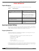
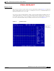
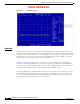
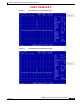
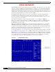
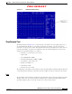

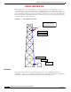
Table Of Contents

PRELIMINARY
D-10
BWX 8415 Basestation Installation and Commissioning Guide
OL-19519-01
Appendix D RF Center Frequency and Interference Analysis Guidelines
Spectrum Analyzer Settings
In the example above, there is 39 dB of loss. In order for the interference measurements to give an
accurate indication of the environmental noise, an additional gain of over 39 dBi would need to be
injected into the test. The best location for the optional LNA would be at the top of the tower prior to the
main run of RF cable. In this location the noise will be amplified prior to the loss through the RF cable.
If the optional LNA is only installed at the lower end of the tower, the noise is reduced by the loss in the
cable and would lose 9 dB of resolution.
Figure D-8 Pre-Installation Test Setup
Procedure
The setup shown in Figure D-8 and the information below are for the initial (pre-installation)
configuration. It gives you a starting point for this procedure. During the later steps, the configuration
will change. Configure the test equipment and antenna as depicted in
Figure D-8.
Test antenna at
Elevation BWX Basestation
Antenna will be installed
Opti on al LNA
RF C able
Optional LNA
Spectr um
Analyz er
RF Cable
Test antenna at
Elevation BWX Basestation
Antenna will be installed
Test antenna at
Elevation BWX Basestation
Antenna will be installed
Opti on al LNAOpti on al LNA
RF C ableRF C able
Optional LNAOpti onal LNA
Spectr um
Analyz er
Spectr um
Analyz er
RF CableRF Cable