
Installation Manual Part 5
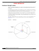
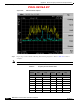

Table Of Contents

PRELIMINARY
D-18
BWX 8415 Basestation Installation and Commissioning Guide
OL-19519-01
Appendix D RF Center Frequency and Interference Analysis Guidelines
Spectrum Analyzer Settings
Frequency Domain Interference Sweeps Analysis
The Frequency Domain Interference Sweep has two kinds of measurements, Max-hold and Single
Sweep. First, we have to determine the theoretical noise floor. We will use the theoretical noise floor to
interpret the Max-hold sweeps data.
Calculating the Theoretical Noise Floor
All analysis of interference is done from the theoretical noise floor. This is the best-case noise floor in
a perfectly clean environment. The following algorithm is used to determine the noise floor.
Theoretical noise floor (NF) = Thermal NF @ 1 Hz and 20° C + sub-carrier
channel energy + Cisco BWX Mobile WiMAX system noise figure
Thermal NF @ 1 Hz and 20° C = -174
Sub-carrier channel energy = 10log(500 KHz) = +57 dB
Cisco BWX Mobile WiMAX system noise figure = +5 dB
Resulting theoretical noise floor
-174+57+5 = -112 dBm
If the setting on the Spectrum Analyzer was 30 KHz and not 500 KHz, there would be a 12 dB difference
in the setting, which means the thermal noise floor for 30 KHz @ 20° C would be –124 dBm.
Analyzing the Max-hold Sweeps
The BWX Basestation is able to correct for a specified level of interference. This level will vary
depending on the type of system or software load that is running on the BWX Basestation.
• Licensed systems (2.3, 2.5, 2.6, 3.5 GHz) +5 dB over theoretical noise floor
This means that any signals on the capture for the Max-hold sweeps above –107 dBm for licensed bands
(0 through –106.9) or –97 for unlicensed bands (0 through –96.9) are not acceptable for spectrum usage
This is summarized below:
• -112 + 5 dB = -107 dB for licensed systems
Note If using 30 KHz for the bandwidth setting on the Spectrum Analyzer, the levels will need to be increased
by 12 dB: -119 dB for licensed systems.
Evaluating the Signal with Additional Gain
So far all of the values that have been discussed – noise floor, signal levels, etc. – have been with no
gains or losses in the test set-up. This will not be the case in the real world. In the data capture, additional
gain was added to the set-up to overcome any losses that are in the system due to cable or connection
losses. When analyzing the interference signals, this additional gain must be removed to determine the
actual interference signal level.