
Installation Manual Part 5
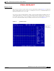
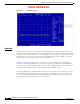
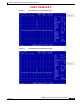
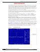

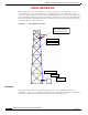
Table Of Contents

PRELIMINARY
D-4
BWX 8415 Basestation Installation and Commissioning Guide
OL-19519-01
Appendix D RF Center Frequency and Interference Analysis Guidelines
Spectrum Analyzer Settings
Figure D-2 -10 Reference Level
Bandwidth
Figure D-2 shows a reference level setting that was manually raised in the Spectrum Analyzer to –10.
The blue line is the display line that was set with the original noise floor at the –50 reference level. When
the reference level was raised from –50 to –10 the displayed noise floor also raised approximately 25 dB
By setting the reference level to a lower value, the Spectrum Analyzer is able to display a noise floor
that is closer to the actual digital noise floor of the equipment.
Figure D-3 and Figure D-4 show the reason the reference level is important for capturing data for
interference measurements. In Figure D-3, the reference was set at –50 dB level. A –65 dB signal was
injected into the Spectrum Analyzer. In Figure D-4 the same –65 dB signal level was injected into the
Spectrum Analyzer, but the reference level was changed from –50 dB to –10 dB.
Figure D-4 still shows the –65 dB signal but only at 18 above the noise floor; whereas Figure D-3 shows
the –65 dB signal at 40 dB above the noise floor. While measuring interference, if the reference level
were set to –10 dB the Spectrum Analyzer would not display any signal levels below the displayed noise
floor level, effectively masking any interference in that area.