
User's Manual
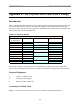


Table Of Contents
- Appendix I: Sample Bill of Materials (BoM)
- Appendix K: RFS System Test (Cable & RFS Sweep)

Navini Networks, Inc. Ripwave Base Station I&C Guide
123
Appendix K: RFS System Test (Cable & RFS Sweep)
Introduction
Before installing the Base Station at a site, the RFS and the associated cables must be tested, and
the results of the tests documented. This procedure applies to the full RFS sub-assembly and
associated cables: data/power cable, RF cables, and the RFS unit. All results are recorded in the
RFS System Test Form P/N 40-00093-00.
Table K1: Pin layout Details
Perform the continuity test with both the Volt Ohm Meter (VOM) and the power/data cable
tester. If the power/data cable tester is not available, perform the continuity test with the VOM.
Required Equipment
• VOM – Continuity tester
• Jumper for shorting pins
• RFS power/data cable tester
Continuity Test With VOM
Step 1. On one end of the cable, short a pair of conductors using a shorting device.
Wire Color Wire Color Signal Name
RED PAIR +12V A
BLACK +12V A RTN
BROWN Heater
DRAIN GND (Shield Wire)
BLACK PAIR RX_EN_B-
WHITE RX_EN_B+
BLUE PAIR RX_EN_A+
BLACK RX_EN_A-
BLACK PAIR Diagbus-
GREEN Diagbus+
BLACK PAIR +12V B Return
YELLOW +12V B
POWER CABLE PIN OUT
A
B
C
D
Circular
Connector(s)
J
K
L
M
E
F
G
H