
User's Manual
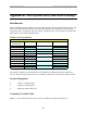


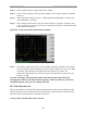

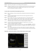
Table Of Contents
- Appendix I: Sample Bill of Materials (BoM)
- Appendix K: RFS System Test (Cable & RFS Sweep)

Navini Networks, Inc. Ripwave Base Station I&C Guide
124
Step 2. Using a VOM/Digital Volt Meter (DVM) set to ohms, verify a short is present on the
pair at the other end.
Step 3. Leaving one probe on one of the paired pins, contact all of the other pins with the other
probe, ensuring an open connection.
Step 4. Check all 6 pairs of wires in the same manner.
Step 5. Verify continuity from the connector case to the drain wire (pin D) on each end of the
cable and between each connector case.
Step 6. Verify an open circuit from the connector case to each individual wire, except to the
drain wire.
Continuity Test With Power/Data Cable Tester
Step 1. Connect one end of the power/data cable to the connector on the power/data cable
tester.
Step 2. Using a VOM/DVM set to ohms, check resistance to ground on the other end of the
cable. Resistance is checked from the case of the connector to the individual pin.
Resistance readings (±10 percent ) are shown in Table K2.
Table K2: Resistance to Ground
Pin Resistance Pin Resistance
A 1K ohms G 6.2K ohms
B 2K ohms H 8.2K ohms
E 3.3K ohms L 10K ohms
F 5.1K ohms M 12K ohms
Step 3. Using a VOM/DVM set to ohms, check resistance between the pairs on the other end
of the cable. Resistance should be the sum of the resistance of the two pairs, ±10
percent. Refer to Table K3.
Table K3: Resistance of Two Pairs
Pins Resistance Pins Resistance
A & B 3K ohms G & H 14.4K ohms
E & F 8.4K ohms L & M 22K ohms
Step 4. Remove the power/data cable tester from the power/data cable.
Sweep Test of RF Cables & RFS
Sweep testing of the RF cables and the RFS is performed in three separate steps.