
User's Manual
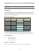


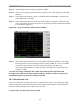

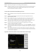
Table Of Contents
- Appendix I: Sample Bill of Materials (BoM)
- Appendix K: RFS System Test (Cable & RFS Sweep)

Navini Networks, Inc. Ripwave Base Station I&C Guide
125
• Sweep of the cables
• Sweep of the RFS
• Sweep of the cables and the RFS together
All results will be entered in the fifth (Cable Loss) and seventh (RFS & Cable Loss) worksheets
of the I&C Closeout Tool, P/N 40-00217-00. The total of the insertion loss for the cables and the
RFS will be equal to the insertion loss of both parts swept together.
Equipment Required
• Signal Generator - Agilent 8648C for 3 GHz / 8648D for 4 GHz, or suitable
alternative, tunable to the RFS center frequency
• Spectrum Analyzer - Agilent E4402B, or equivalent
• Signal Generator cable and Spectrum Analyzer cable – Gender can be changed using
a barrel connector
• Male and Female barrel connectors for Signal Generator cable and Spectrum
Analyzer cable connections
• Power/data test cable
• Navini RFS Test Box
Equipment Settings
Spectrum Analyzer:
• Span – 5 MHz
• RBW – 100 KHz
• VBW – 100 KHz
• Sweep Time – Auto
• Frequency (Provided in Table L4)
Signal Generator:
• Amplitude – 0 dB (except for the Tx side of the RFS Sweep in a TTA system, where
the amplitude of the Signal Generator must be set to –20 dBm)
• Frequency (Provided in Table O4)
Test Setup
When performing each type of sweep, the sweep has to be performed at certain frequency
intervals (Table K4). Perform the complete test at the first frequency. Go to the next frequency
and recalibrate the test setup. Perform the complete test again. Do the same for the third
frequency. Refer to Figure K2.
Table K4: Sweep Frequencies
System Low Medium High
2.3 GHz (Low band)
2305.00 2312.50 2316.75