
User's Manual


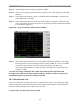

Table Of Contents
- Appendix I: Sample Bill of Materials (BoM)
- Appendix K: RFS System Test (Cable & RFS Sweep)

Navini Networks, Inc. Ripwave Base Station I&C Guide
127
Step 3. Set the Signal Generator output amplitude to 0 dBm.
Step 4. Set the center frequency of the Spectrum Analyzer to the center frequency of the RFS
under test.
Step 5. Set the Spectrum Analyzer to Span = 5 MHz, Resolution Bandwidth = 100 kHz, and
Video Bandwidth = 100 kHz.
Step 6. Take a marker measurement on the Spectrum Analyzer by using the ‘marker to peak’
or the ‘peak search’ function. The screen on the Spectrum Analyzer should look similar
to that shown in Figure K3.
Figure K3: Sweep Test Marker Measurement Example
Step 7. If the marker measurement doesn’t read 0.0 dBm, adjust the amplitude on the Signal
Generator until the Spectrum Analyzer marker reads 0.0 dBm, or as close to 0.0 dBm
as possible. This will remove all losses associated with the test cables. All
measurement data should be recorded one digit to the right of the decimal point, for
example, 31.5dB.
Once the test setup is calibrated, these cables will remain in place and will be used
throughout the whole test at this particular frequency. If the test cables are removed or
changed during the test, incorrect readings will result.
RF Cable Insertion Loss
This test is performed on all RF cables that are installed in the system. This includes the eight
antenna cables, the system calibration cable, and all jumper cables. Follow the procedures for
either the cables on the ground or cables run up the tower.
Test Procedure For RF Cables on the Ground