
User's Manual
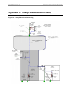
Table Of Contents
- Export BTS Data
- Perform the Calibration Verification Procedure
- Single Antenna Element Test
- Install & Test Customer EMS Operations
- Perform Calibration Using Customer’s EMS
- Verify System Performance
- Verify System Operation With Multiple Modems
- Back Up EMS Database
- Customer Acceptance
- Appendix C: BTS Specifications
- Appendix G: Sample Base Station Drawing
- Appendix H: Antenna Power & Cable Selection

Navini Networks, Inc. Ripwave Base Station I&C Guide
99
backhaul, refer to the Regulatory Information in Chapter 1, Page 8 – specifically regarding
cabling to Ethernet or T1/E1 backhauls. Ethernet connections require a UL497B listed protection
device to be installed between the BTS and the first network device. T1/E1 connections must be
routed from the BTS through a UL497 listed protection device at the demarcation point. The
interconnect cables for T1/E1 backhauls must be a minimum #26 AWG wire, in accordance with
NEC/CEC standards. If the customer’s EMS is already installed and has been used for testing
purposes, skip to the “Verify System Performance” section of this chapter.
Install EMS Software
The EMS software installation procedures can be found in the EMS Software Installation Guide,
P/N 40-00017-00. After installing the EMS Server and Client applications, the EMS needs to be
configured with the settings that are designated for the Base Station. The settings are found in the
Network Architecture Plan provided by the customer.
Ensure connection between the Base Station and the backhaul. The connection to the Base
Station will be either an Ethernet connection or T1 connections.
Verify EMS to Base Station Connectivity
Follow the steps below to ensure the EMS and Base Station can communicate.
Step 1. Open a Command Prompt window on the computer where the EMS is installed.
Step 2. Ping the Base Station using the CLI command ping <base station ip address>. Verify
that a reply from the Base Station is received.
Perform Calibration Using Customer’s EMS
This step is necessary only if you have been using a Test EMS up to this point. You will need to
install the customer’s EMS server and software. Calibrate the Base Station using the customer’s
EMS. Follow the same calibration procedures described earlier in this chapter, Calibrate the Base
Station. Perform the procedure three times and make sure that the results are stable (±3).