
User's Manual
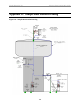
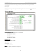
Table Of Contents
- Export BTS Data
- Perform the Calibration Verification Procedure
- Single Antenna Element Test
- Install & Test Customer EMS Operations
- Perform Calibration Using Customer’s EMS
- Verify System Performance
- Verify System Operation With Multiple Modems
- Back Up EMS Database
- Customer Acceptance
- Appendix C: BTS Specifications
- Appendix G: Sample Base Station Drawing
- Appendix H: Antenna Power & Cable Selection

Navini Networks, Inc. Ripwave Base Station I&C Guide
106
Appendix H: Antenna Power & Cable Selection
Non-TTA Systems
Overview
There are 3 types of cables that are part of a non-TTA Base Station installation: antenna (RF)
cables, calibration (CAL) cable, and data/power cable (not used with the TTA systems). In
addition both the RF and CAL cables are made of a longer Main segment, which typically
consists of a low-loss but heavier and less rigid cable and two shorter Jumper cables (one
connecting the Main segment to the RFS and the other connecting the main segment to the BTS),
which typically have a higher loss, but are lighter and more flexible.
The RF cables are eight coaxial cables that carry RF signals between the BTS and the RFS. The
CAL cable is a single coaxial cable that provides a common second path for the RF signals
between the BTS and the RFS for system calibration.
The RF cable paths and the CAL cable path are interconnected through the Cal Board located in
the RFS. The Cal Board introduces a loss of 27 to 31 dB between the common Cal Cable path
and each RF Cable path. As a result of this, most of the power sent to or received at the antenna
elements travels through the RF Cable paths, and only a small fraction of it is derived to the CAL
Cable path.
The purpose of this section is to describe the calculations used to determine the combinations of
Main and Jumper Cables that are adequate for a particular system. This determination is made
taking into consideration the operating frequency band of the system, the maximum output
power that the RF/PA cards can deliver, the maximum and minimum power level that the SYN
card can output or accept as input during calibration, the losses introduced by the cables and the
different system components that the RF signal must go through, etc. I some cases the number
of subcarrriers, whether FCC regulations apply, whether a Standard Filter in the back of the BTS
is used or not, the weight of the cables on the tower and the bent radius of the main cables must
also be taken into consideration.
The calculations described in this section are performed automatically by an Excel spreadsheet.
It is assumed here that the same combination of Main and Jumper cables will be used for the RF
and CAL paths.
The power and data cable is only taken into consideration if the weight of the cables on the tower
must be kept below a certain allowed maximum.