
User's Guide
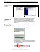
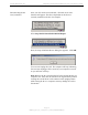
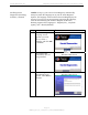
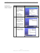
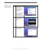
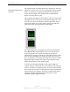
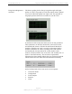
Table Of Contents
- Permissions, Trademarks & Distribution
- Safety
- Regulatory Information
- Introduction
- Package Inventory
- Ripwave Models
- Minimum Computing Requirements
- Physical Characteristics
- Installing the PC Card on Windows 2000
- Accessing the Internet
- Disconnecting the PC Card
- Indicator Light
- Troubleshooting
- Installing Navini Diagnostics (NavDiag) Software
- Using Navini Diagnostics
- Uninstalling Navini Diagnostics Software
- Optional Desktop Antenna
- Care and Maintenance
- Upgrading the PC Card
- ADDENDUM 1: PC Card - PC Troubleshooting
- ADDENDUM 2: End User Software License Agreement

Navini Networks, Inc. Ripwave Wireless Broadband Access Card User’s Guide
Page 20
050525_pv1.2_PC_Card_User’s_Guide_40-00292-00b(4.3)
Using Navini Diagnostics,
continued
The History graphs plot the change in signal strength and signal
quality over time. The graphs cover the last minute and are updated
every second. Read the graphs from right to left. The right side of
the graph represents the most recent status of your PC Card.
At the bottom of the Connection Status screen are four parameters.
These parameters are BTS ID, Network ID, Active SW Version,
and Standby SW Version. The BTS ID and Network ID indicate
the BTS to which the PC Card is currently synchronized and the
network in which the PC Card is operating. Active SW Version
and Standby SW Version indicate the version number of the
software currently loaded in the “active side” and “standby side” of
the PC Card’s flash memory. The two letters in parenthesis
following the release number indicate the type of software load. JD
indicates Joint Detection while EN indicates Enhanced Nulling.
On the left-hand side of the screen are five screen options:
Connection Status
Configuration
Trend Analysis
Statistics
About