GETTING STARTED GUIDE Cisco 2500 Series Wireless Controller May 2011 Revised June 2, 2011 1 About This Guide 2 Unpacking and Preparing the Controller for Operation 3 Installing the Controller 4 Running the Bootup Script and Power-On Self Test 5 Logging into the Controller 6 Connecting to the Network 7 What’s New in Cisco Product Documentation 8 Translated Safety Warnings
1 About This Guide This guide is designed to help you install and minimally configure your Cisco 2504 Wireless Controller (2504 controller), which is part of the Cisco 2500 Series Wireless Controllers. FCC Safety Compliance Statement This equipment has been tested and found to comply with the limits for a Class B digital device, pursuant to Part 15 of the FCC Rules. These limits are designed to provide reasonable protection against harmful interference in a residential installation.
Warning There is the danger of explosion if the battery is replaced incorrectly. Replace the battery only with the same or equivalent type recommended by the manufacturer. Dispose of used batteries according to the manufacturer’s instructions. Statement 1015 Warning This equipment must be grounded. Never defeat the ground conductor or operate the equipment in the absence of a suitably installed ground conductor.
Note Direct connection of access points to Cisco 2500 Series Wireless Controllers are not currently supported. The 2504 controller offers robust coverage with 802.11 a/b/g and delivers unprecedented reliability using 802.11n with Cisco Next-Generation Wireless Solutions and Cisco Enterprise Wireless Mesh. To best use this guide, you should have already designed the wireless topology of your network and have a working knowledge of how controllers function in a wireless LAN network.
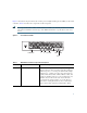
Figure 2 shows the front panel and location of the ports and light-emitting diodes (LEDs) for the 2504 controller. Table 1 describes the components of the front panel. Note It is expected that there will be small variations in LED color intensity and hue from unit to unit. This is within the normal range of the LED manufacturer’s specifications and is not a defect.
Callout Port and LEDs State and Description 1 GigE port and LED The Gigabit Ethernet port is an RJ-45 connector form-factor. This port is designed so that 1500 VAC rms isolation (per the 802.3 specification) is met between chassis ground and any 48V/Ethernet signal. LED description: • Green or Blinking Green—Link activity • Off—No link 2 GigE port and LED The Gigabit Ethernet port is an RJ-45 connector form-factor. This port is designed so that 1500 VAC rms isolation (per the 802.
Callout Port and LEDs State and Description RESET Reset button Pushing the Reset button reboots the system. PWR Power LED The power LED light is on when all the power conversion circuits are running normally. LED description: • Green—Power is on • Off—No power to the system SYS System LED The system LED determines if the system is powered up. LED description: • Blinking Amber—Boot-loader is active and waiting for user input from the system console. • Blinking Green—Boot-loader or booting.
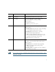
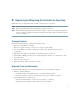
Note Wait at least 20 seconds before reconnecting an access point to the controller. Otherwise, the controller may fail to detect the device. Figure 3 shows the back panel and identifies its components. Table 2 describes the back panel components. Controller Back Panel and Components 282250 Figure 3 Cable Lock Slot POWER 48VDC Table 2 Controller Back Panel and Component Descriptions Ports and Slots State and Description POWER 48VDC The 48 V input power is provided via an external AC/DC adapter.
2 Unpacking and Preparing the Controller for Operation Follow these steps to unpack the 2504 controller and prepare it for operation: Step 1 Open the shipping container and carefully remove the contents. Step 2 Return all packing materials to the shipping container and save it. Step 3 Ensure that all items listed in the “Package Contents” section are included in the shipment. Check each item for damage. If any item is damaged or missing, notify your authorized Cisco sales representative.
• Local TFTP server (required for downloading operating system software updates). Cisco uses an integral TFTP server. This means that third-party TFTP servers cannot run on the same workstation as the Cisco WCS because Cisco WCS and third-party TFTP servers use the same communication port. Initial System Configuration Information Obtain the following initial configuration parameters from your wireless LAN or network administrator: • A system (controller name), such as controller.
• RADIUS server IP address, communications port, and secret if you are configuring a RADIUS server, such as 10.40.0.3, 1812, and mysecretcode. • The country code for this installation. Enter help to see a list or refer to the Cisco Wireless LAN Controller Configuration Guide for country code information. This guide is available at cisco.com. • Status of the 802.11a, 802.11b, 802.11g, or 802.11n networks, either enabled or disabled. • Status of Radio Resource Management (RRM), either enabled or disabled.
• Mounting the Controller on a Wall (Rack-Mount Brackets) • Mounting the Controller on a Wall (Mounting Screws) • Mounting the Controller in a Rack Mounting the Controller on a Desktop or Shelf Before mounting the controller on a desktop or shelf, install the rubber feet located in accessory kit shipped with the controller. To install the rubber feet to the controller, follow these steps: Step 1 Locate the adhesive strip with the rubber feet in the mounting-kit envelope.
Step 3 Place the switch on the table or shelf near an AC power source. Note Step 4 Allow 3 inches of space around the controller ventilation openings to prevent airflow restriction and overheating.
Figure 5 Installing the Rack-Mount Brackets to the Sides of the Controller 282083 1 BASE MOUNT 1 1 #10-32 flat head screws (mounting screws for each side of the controller) Step 2 Mount the 2504 controller on the wall with the front panel facing down, as shown Figure 6. For the best support of the controller and cables, make sure the controller is attached securely to wall studs or to a firmly attached plywood mounting backboard.
Mounting the Controller on the Wall 1 1 Front panel (facing down) 2 #10-32 flat head screws Step 3 2 3 3 282085 Figure 6 Wall mounting screws After the controller is mounted on the wall, perform the following tasks to complete the installation: • Connecting the Controller Console Port • Securing the Power Adapter Cable • Connecting to the Network Step 4 For configuration instructions about using the CLI setup program, see the “Running the Bootup Script and Power-On Self Test” section on page
Warning Read the wall-mounting carefully before beginning installation. Failure to use the correct hardware or to follow the correct procedures could result in a hazardous situation to people and damage to the system. Statement 378 To mount the controller on a wall using mounting screws, follow these steps: Step 1 Figure 7 Mark the location of the mounting screws on the wall. Use the mount hole locations on the back of the controller for placement of the mounting screws (Figure 7).
Place the controller onto the mounting screws and slide it down until it lock into place, as shown in Figure 8. Note Figure 8 The front panel of the controller should be facing down.
Step 6 For configuration instructions about using the CLI setup program, see the “Running the Bootup Script and Power-On Self Test” section on page 23. Mounting the Controller in a Rack To mount the 2504 controller in a 19-inch equipment rack, you can order an optional Optional Rack Mount kit (AIR-CT2504-RMNT). Warning To prevent bodily injury when mounting or servicing this unit in a rack, you must take special precautions to ensure that the system remains stable.
Figure 9 Attaching the 19-Inch Brackets to the Side of the Controller. 282082 1 RACK MOUNT 1 1 #10-32 flat head screws (mounting screws for each side of the controller) Step 2 After the brackets are attached to the sides of the controller, insert the controller into the 19-inch rack. Use either the 10-32 pan-head screws or the 12-24 slotted head screws to secure the controller in the rack, as shown in Figure 10.
Figure 10 Mounting the Controller in a 19-Inch Rack 282086 1 1 Step 3 #10-32 pan-head screws or #12-24 slotted head screws After the controller is mounted in the rack, perform the following tasks to complete the installation: • Connecting the Controller Console Port • Securing the Power Adapter Cable • Connecting to the Network Step 4 20 For configuration instructions about using the CLI setup program, see the “Running the Bootup Script and Power-On Self Test” section on page 23.
Connecting the Controller Console Port Caution Do not connect a Power over Ethernet (PoE) cable to the console port. Doing so will damage the controller. Before you can configure the 2504 controller for basic operations, you need to connect it to a PC that uses a VT-100 terminal emulator (such as HyperTerminal, ProComm, Minicom, or Tip).
Step 1 Wrap the power adapter cable through the plastic security clip as shown in Figure 11. Plastic Relief Clip 281917 Figure 11 Step 2 Fasten the security clip with a screw to the existing hole on the back panel on the 2504 controller (see Figure 12).
Security clip secured with screw 1 2 3 Power plugged into the POWER 48VDC port. AC/DC power adapter cable Installing a Security Lock The controller has a security slot on the back panel. You can install an optional customer-supplied cable lock, such as the type that is used to secure a laptop computer, to secure the controller. Refer to Figure 3 for the location of the security lock.
Step 3 Observe the bootup using the CLI screen. The bootup script displays operating system software initialization (code download and POST verification) and basic configuration as shown in the following bootup display example: CISCO SYSTEMS WLCNG Boot Loader Version 1.0.15 (Built on Nov 23 2010 at 07:51:36 by cisco) Board Revision 0.0 (SN: PSJ143302MT, Type: AIR-CT2504-K9) (P) Verifying boot loader integrity... OK. OCTEON CN5230C-SCP pass 2.
compress = none ifconfig: SIOCGIFFLAGS: No such device Detecting Hardware ... Installing ether-pow driver - 0x6008 starting pid 805, tty '/dev/ttyS0': '/usr/bin/gettyOrMwar' Cryptographic library self-test....passed! XML config selected Validating XML configuration octeon_device_init: found 1 DPs /dev/fpga: No such device or address readCPUConfigData: cardid 0x6060001 Cisco is a trademark of Cisco Systems, Inc. Software Copyright Cisco Systems, Inc. All rights reserved. Cisco AireOS Version 7.0.114.
Starting Policy Manager: ok Starting Authentication Engine: ok Starting Mobility Management: ok Starting Virtual AP Services: ok Starting AireWave Director: ok Starting Network Time Services: ok Starting Cisco Discovery Protocol: ok Starting Broadcast Services: ok Starting Logging Services: ok Starting DHCP Server: ok Starting IDS Signature Manager: ok Starting RFID Tag Tracking: ok Starting Power Supply and Fan Status Monitoring Service: ok Starting Mesh Services: ok Starting TSM: ok Starting CIDS Services
Step 5 Continue booting the controller or press Esc to access the following menu: 1. Run primary image (7.0.114.76) - Active 2. Run backup image (7.0.114.75) 3. Change active boot image 4. Clear configuration 5. Format FLASH Drive 6. Manually update images -----------------------------------------------------------Enter selection: If you did not press Esc, the boot process continues and takes two to three minutes. Do not reboot the controller until the user login prompt appears. Loading primary image (7.
Starting Fastpath DP Heartbeat : ok Fastpath CPU00: Starting Fastpath Application. SDK-1.8.0, build 269. Flags-[DUTY CYCLE] : ok Fastpath CPU00: Initializing last packet received queue. Num of cores(2) Fastpath CPU00: Init MBUF size: 1856, Subsequent MBUF size: 2040 Fastpath CPU00: Core 0 Initialization: ok Fastpath CPU00: Initializing Timer... Fastpath CPU01: Core 1 Initialization: ok Fastpath CPU00: Initializing Timer...done.
CLI: ok Secure Web: Web Authentication Certificate not found (error). If you cannot access management interface via HTTPS please reconfigure Virtual Interface. License Agent: ok (Cisco Controller)> Step 6 If the controller passes the POST, the bootup script runs the Startup Wizard, which prompts you for basic configuration information.
Note Table 3 Press the hyphen key if you need to return to the previous command line. Startup Wizard Information Wizard Setting Action System Name Enter the system name, which is the name you want to assign to the controller. You can enter up to 31 ASCII characters. Administrative user name Enter the administrative user name to be assigned to this controller. You can enter up to 24 ASCII characters for each. The default administrative username is admin.
Table 3 Startup Wizard Information (continued) Wizard Setting Action Management Interface DHCP Server IP Address Enter the management interface DHCP server IP address. Virtual Gateway IP Address Enter the IP address of the controller virtual interface. You should enter a fictitious, unassigned IP address, such as 1.1.1.1. The virtual interface is used to support mobility management, DHCP relay, and embedded Layer 3 security such as guest web authentication and VPN termination.
Table 3 Startup Wizard Information (continued) Wizard Setting Action Allow Static IP Addresses Enter YES to allow clients to assign their own IP address or no to make clients request an IP address from a DHCP server. Values are YES or no. The default setting is YES.
Table 3 Startup Wizard Information (continued) Wizard Setting Action Enter a polling interval between 3600 and 604800 secs Enter the polling interval between 3600 and 604800 seconds. Note Configuration correct? This prompt only displays if YES was entered in the “Configure a NTP Server Now?” prompt. Enter yes if the configuration entered is correct. Values are yes and no. If yes is entered. the controller saves your configuration, reboots, and prompts you to log in.
Step 2 The CLI displays the root level system prompt: #(system prompt)> The system prompt can be any alphanumeric string up to 31 characters. You can change it by entering the config prompt command. For example, to change the system prompt to CISCO2504, enter config prompt "CISCO2504" and press Enter. Make sure you enter the new prompt using double quotation marks. Note The CLI automatically logs out without saving any changes after 5 minutes of inactivity.
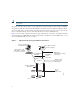
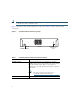
Note If the link does not activate, check the cable. When you are connecting to a hub or a switch, use a straight-through cable. Connecting Access Points After you have configured the controller, use Category-5, Category-5e, Category-6, or Category-7 Ethernet cables to connect up to 50 Cisco lightweight access points to the controller Ethernet ports or to the network (distribution system) as shown in Figure 14.
Figure 14 Access Points Connected to a Controller Network 10/100/1000BASE-T MDI cable Cisco 2504 Wireless Controller Network Cisco Access Points 282081 10/100/1000BASE-T MDI cables Checking the Controller LEDs If your 2504 controller is not working properly, check the LEDs on the front panel of the unit. You can use the LED indications to quickly assess the status of the unit. See Table 1 on page 5 for a description of the front panel LEDs. The installation is complete.
Step 2 Press and hold the Reset button for at least 3 seconds using a pointed object, such as a ball point pen, pencil, or paper clip. Step 3 After the controller reboots, enter your username and password at the prompts. If you have configured the controller, it reboots and loads the configuration. If you have not configured the controller, the configuration wizard appears.
8 Translated Safety Warnings Statement 1071—Warning Definition Warning IMPORTANT SAFETY INSTRUCTIONS This warning symbol means danger. You are in a situation that could cause bodily injury. Before you work on any equipment, be aware of the hazards involved with electrical circuitry and be familiar with standard practices for preventing accidents. Use the statement number provided at the end of each warning to locate its translation in the translated safety warnings that accompanied this device.
Attention IMPORTANTES INFORMATIONS DE SÉCURITÉ Ce symbole d'avertissement indique un danger. Vous vous trouvez dans une situation pouvant entraîner des blessures ou des dommages corporels. Avant de travailler sur un équipement, soyez conscient des dangers liés aux circuits électriques et familiarisez-vous avec les procédures couramment utilisées pour éviter les accidents.
Advarsel VIKTIGE SIKKERHETSINSTRUKSJONER Dette advarselssymbolet betyr fare. Du er i en situasjon som kan føre til skade på person. Før du begynner å arbeide med noe av utstyret, må du være oppmerksom på farene forbundet med elektriske kretser, og kjenne til standardprosedyrer for å forhindre ulykker. Bruk nummeret i slutten av hver advarsel for å finne oversettelsen i de oversatte sikkerhetsadvarslene som fulgte med denne enheten.
Varning! VIKTIGA SÄKERHETSANVISNINGAR Denna varningssignal signalerar fara. Du befinner dig i en situation som kan leda till personskada. Innan du utför arbete på någon utrustning måste du vara medveten om farorna med elkretsar och känna till vanliga förfaranden för att förebygga olyckor. Använd det nummer som finns i slutet av varje varning för att hitta dess översättning i de översatta säkerhetsvarningar som medföljer denna anordning.
Statement 1015—Battery Handling Warning There is the danger of explosion if the battery is replaced incorrectly. Replace the battery only with the same or equivalent type recommended by the manufacturer. Dispose of used batteries according to the manufacturer’s instructions. Statement 1015 Waarschuwing Er is ontploffingsgevaar als de batterij verkeerd vervangen wordt. Vervang de batterij slechts met hetzelfde of een equivalent type dat door de fabrikant aanbevolen is.
¡Advertencia! Varning! Existe peligro de explosión si la batería se reemplaza de manera incorrecta. Reemplazar la batería exclusivamente con el mismo tipo o el equivalente recomendado por el fabricante. Desechar las baterías gastadas según las instrucciones del fabricante. Explosionsfara vid felaktigt batteribyte. Ersätt endast batteriet med samma batterityp som rekommenderas av tillverkaren eller motsvarande. Följ tillverkarens anvisningar vid kassering av använda batterier.
Statement 1024—Ground Conductor Warning Waarschuwing This equipment must be grounded. Never defeat the ground conductor or operate the equipment in the absence of a suitably installed ground conductor. Contact the appropriate electrical inspection authority or an electrician if you are uncertain that suitable grounding is available. Statement 1024 Deze apparatuur dient geaard te zijn.
Advarsel Aviso 50 Dette utstyret må jordes. Omgå aldri jordingslederen og bruk aldri utstyret uten riktig montert jordingsleder. Ta kontakt med fagfolk innen elektrisk inspeksjon eller med en elektriker hvis du er usikker på om det finnes velegnet jordning. Este equipamento deve ser aterrado. Nunca anule o fio terra nem opere o equipamento sem um aterramento adequadamente instalado.
Statement 1040—Product Disposal Warning Waarschuwing Varoitus 52 Ultimate disposal of this product should be handled according to all national laws and regulations. Statement 1040 Het uiteindelijke wegruimen van dit product dient te geschieden in overeenstemming met alle nationale wetten en reglementen. Tämä tuote on hävitettävä kansallisten lakien ja määräysten mukaisesti.
Avvertenza Lo smaltimento di questo prodotto deve essere eseguito secondo le leggi e regolazioni locali. Advarsel Endelig kassering av dette produktet skal være i henhold til alle relevante nasjonale lover og bestemmelser. Aviso ¡Advertencia! Varning! Deitar fora este produto em conformidade com todas as leis e regulamentos nacionais. Al deshacerse por completo de este producto debe seguir todas las leyes y reglamentos nacionales.
Statement 371—Power Cable and AC Adapter When installing the product, please use the provided or designated connection cables/power cables/AC adaptors/batteries. Using any other cables/adaptors could cause a malfunction or a fire. Electrical Appliance and Material Safety Law prohibits the use of UL-certified cables (that have the “UL” or “CSA” shown on the cord), not regulated with the subject law by showing “PSE” on the cord, for any other electrical devices than products designated by Cisco.
Cisco and the Cisco Logo are trademarks of Cisco Systems, Inc. and/or its affiliates in the U.S. and other countries. A listing of Cisco's trademarks can be found at www.cisco.com/go/trademarks. Third party trademarks mentioned are the property of their respective owners. The use of the word partner does not imply a partnership relationship between Cisco and any other company. (1005R).