
User Guide

1-18
Catalyst 2960 Switch Hardware Installation Guide
OL-7075-05
Chapter 1 Product Overview
Rear Panel Description
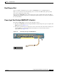
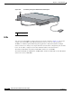
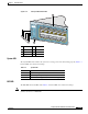
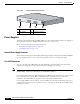
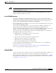
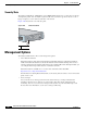
Figure 1-19 Catalyst 2960 Switch Rear Panel
Power Supplies
All switches other than the Catalyst 2960PD-8TT-L are powered through their internal power supply (see
“Power Input Port (Catalyst 2960PD-8TT-L Switch)” section on page 1-11).
These sections describe the power connection options:
• Internal Power Supply Connector, page 1-18
• Cisco RPS Connectors, page 1-18
Internal Power Supply Connector
The internal power supply is an autoranging unit that supports input voltages between 100 and 240 VAC.
Use the supplied AC power cord to connect the AC power connector to an AC power outlet.
Cisco RPS Connectors
You can connect the Cisco RPS 2300 or the Cisco RPS 675 to provide backup power if the switch
internal power supply fails on those switches that have an RPS power connector.
Note These Catalyst 2960 switches do not have an RPS connector: Catalyst 2960-8TC-L, 2960G-8TC-L,
2960PD-8TT-L, 2960-24-S, 2960-24TC-S, and 2960-48TC-S switches.
Connect the switch and the Cisco RPS 2300 or the Cisco RPS 675 to the same AC power source. See the
Cisco redundant power systems (RPS) compatibility matrix documents on Cisco.com for more
information about which RPS are supported on each of the Catalyst 2960 switches.
Use the supplied RPS connector cable to connect the RPS to the switch. For information about power
requirements for the remote power system that you are connecting, see the hardware installation guide
for that power system.
1 RJ-45 console port 3 RPS connector
2 Fan exhaust 4 AC power connector
C
O
N
S
O
L
E
1 2 3 4
137071