Cisco Catalyst Switch Module 3110G, 3110X, and 3012 for IBM BladeCenter Hardware Installation Guide April 2008 Americas Headquarters Cisco Systems, Inc. 170 West Tasman Drive San Jose, CA 95134-1706 USA http://www.cisco.
THE SPECIFICATIONS AND INFORMATION REGARDING THE PRODUCTS IN THIS MANUAL ARE SUBJECT TO CHANGE WITHOUT NOTICE. ALL STATEMENTS, INFORMATION, AND RECOMMENDATIONS IN THIS MANUAL ARE BELIEVED TO BE ACCURATE BUT ARE PRESENTED WITHOUT WARRANTY OF ANY KIND, EXPRESS OR IMPLIED. USERS MUST TAKE FULL RESPONSIBILITY FOR THEIR APPLICATION OF ANY PRODUCTS.
C O N T E N T S Preface vii Audience Purpose vii vii Conventions vii Related Publications viii Obtaining Documentation, Obtaining Support, and Security Guidelines CHAPTER 1 Product Overview Switch Modules 1-1 1-1 Hardware Features 1-2 10/100/1000 Ethernet Ports 1-3 10-Gigabit Ethernet Module Slot 1-4 Port Numbering 1-4 Internal 100BASE-T Ethernet Management Port Switch Module LEDs 1-5 StackWise Plus Ports 1-9 Console Port 1-9 Management Options 1-9 Network Configurations CHAPTER 2 viii Swit
Contents Connecting Devices to the Ethernet Ports Where to Go Next CHAPTER Troubleshooting 3 2-13 2-13 3-1 Diagnosing Problems 3-1 Verify Switch Module POST Results 3-1 Verify Switch Module LEDs 3-1 Verify Switch Module Connections 3-2 Verify Switch Module Performance 3-4 Resetting the Switch Module 3-4 Using the Mode Button to Reset the Switch Module How to Replace a Failed Stack Member APPENDIX A Technical Specifications APPENDIX B Connector and Cable Specifications 3-5 3-5 A-1 B-1 Conn
Preface Audience This guide is for the networking or computer technician responsible for installing a Cisco Catalyst switch module. We assume that you are familiar with the concepts and terminology of Ethernet and local area networking. Purpose This guide documents the hardware features of the Cisco Catalyst Switch Module 3110G, 3110X, and 3012 for IBM BladeCenter—referred to as the switch module.
Preface Warning This warning symbol means danger. You are in a situation that could cause bodily injury. Before you work on any equipment, be aware of the hazards involved with electrical circuitry and be familiar with standard practices for preventing accidents. Use the statement number provided at the end of each warning to locate its translation in the translated safety warnings that accompanied this device.
CH A P T E R 1 Product Overview The Cisco Catalyst Switch Module 3110G, 3110X, and 3012 for IBM BladeCenter—referred to as the switch modules—are Ethernet switch modules that you install in an IBM BladeCenter enclosure—referred to as the blade enclosure. You can connect devices to the switch modules for connections to other network devices such as routers, servers, and other switches. The Catalyst Switch Module 3110G and 3110X support stacking through Cisco StackWise Plus technology.
Chapter 1 Product Overview Hardware Features Table 1-1 Catalyst Switch Module 3110G, 3110X, and 3012 (continued) Switch Model Cisco Part Number Catalyst Switch WS-CBS3110X-S Module 3110X IBM Part Number Description WS-CBS3110X-S-I 1 external 10-Gigabit Ethernet module slot, 14 internal 1000BASE-X Ethernet downlink ports, 1 internal 100BASE-T Ethernet management port, 2 StackWise Plus ports Catalyst Switch WS-CBS3012-IBM WS-CBS3012-IBM-I Module 3012 4 external 10/100/1000BASE-T Ethernet ports, 1
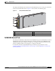
Chapter 1 Product Overview Hardware Features The Catalyst Switch Module 3012 includes the 10/100/1000 Ethernet ports, console port, release latch, and the switch module LEDs shown in Figure 1-2 and described on the following pages.
Chapter 1 Product Overview Hardware Features 10-Gigabit Ethernet Module Slot The Catalyst Switch Module 3110X 10-Gigabit Ethernet module slot is used for an uplink connection to other switches and routers. The module slot operates in full-duplex mode and uses the hot-swappable Cisco X2 transceiver modules. The X2 transceiver modules have a dual SC/PC connector (-SR, -LX4) or an Infiniband 4x connector (-CX4) for connections to multimode fiber (MMF), single-mode fiber (SMF), or 4x Infiniband cable.
Chapter 1 Product Overview Hardware Features Switch Module LEDs You can use the switch module LEDs to monitor switch module activity. Figure 1-3 shows the switch module LEDs and the Mode button that you use to activate the different modes.
Chapter 1 Product Overview Hardware Features Mode Button The fault/stack or stack member LEDs are selected by using the Mode button. If the mode LED for a particular mode is solid green, that mode is currently selected, and the other mode LEDs are off (only Catalyst Switch Module 3110G and 3110X). To select or change a mode, use a small pointed object to press the Mode button until the desired mode is selected.
Chapter 1 Product Overview Hardware Features Fault/Stack Mode LED The fault/stack mode LED shows either a fault condition or the switch stack status, depending on the Mode button selection. When the switch module is not stacked and there is no fault, the LED is off. If the switch module is stacked and the stack mode LED is selected, the stack member LED is active. Table 1-5 lists the LED colors and their meanings (only Catalyst Switch Module 3110G and 3110X).
Chapter 1 Product Overview Hardware Features Port LEDs The Catalyst Switch Module 3110G and 3012 port LEDs show interface activity and link status. Table 1-8 lists the LED colors and their meanings. Table 1-8 Catalyst Switch Module 3110G and 3012 Port LEDs Color Activity LED Description Link Status LED Description Off No activity. No link, or port was administratively shut down. Green — Link present, or the port might be blocked by Spanning Tree Protocol (STP) and is not forwarding data.
Chapter 1 Product Overview Management Options When stack mode is selected on a Catalyst Switch Module 3110X, the two port status LEDs show the status for StackWise Plus ports 1 and 2, respectively. Table 1-11 lists the LED colors and their meanings. Table 1-11 Catalyst Switch Module 3110X Port Status LEDs with Stack Mode Selected Color Port Status LED Description Off No link. Green Switch stack link is active.
Chapter 1 Product Overview Management Options • IBM Director For standalone switch modules, you can use the IBM Director to view the hardware configuration of remote systems, monitor the usage and performance of critical components, centrally manage individual or large groups of IBM and non-IBM Intel®-processor-based servers, desktop computers, workstations, and mobile computers on a variety of platforms. See the IBM documentation for more information.
CH A P T E R 2 Switch Module Installation This chapter describes how to install the Catalyst Switch Module 3110G, 3110X, and 3012 and make connections to the switch module. It also includes planning and cabling considerations for stacking switch modules.
Chapter 2 Switch Module Installation Preparing for Installation Warning Ethernet cables must be shielded when used in a central office environment. Statement 171 Warning Do not reach into a vacant slot or chassis while you install or remove a module or a fan. Exposed circuitry could constitute an energy hazard. Statement 206 Warning Do not work on the system or connect or disconnect cables during periods of lightning activity.
Chapter 2 Switch Module Installation Preparing for Installation Installation Guidelines Note This product is not intended to be connected directly or indirectly by any means whatsoever to interfaces of public telecommunications networks. Consider these guidelines before you install the switch module: • Fill any unoccupied interconnect bays or any unoccupied power module bays in the blade enclosure with filler modules. • Identify the bays in which you will insert the switch modules.
Chapter 2 Switch Module Installation Installing the Switch Module Installing the Switch Module This section covers switch module installation. The illustrations in this section show the Catalyst Switch Module 3110G. The instructions are the same for the Catalyst Switch Module 3110X and 3012. Follow these steps: Step 1 Remove the acoustic attenuation module, if one is installed, from the rear of the blade enclosure.
Chapter 2 Switch Module Installation Installing the Switch Module Step 7 Slide the switch module into the bay until it stops (Figure 2-2). Figure 2-2 Installing the Switch Module C O N S O LM EO D E ! M B R M S T LNK 15 ACT LNK 16 ACT LNK 17 ACT LNK 1 STA CK 2 Step 8 201897 18 ACT Move the switch module release latch to the closed position. After you insert and lock the switch module, it turns on, and the power-on self-test (POST) runs to verify that the switch module is operating correctly.
Chapter 2 Switch Module Installation Creating Switch Stacks Creating Switch Stacks This section is only for Catalyst Switch Module 3110G and 3110X and is optional. A switch stack is a set of up to nine stacking-capable switch modules that are connected through their StackWise Plus ports. One switch module controls the operation of the stack and is called the stack master. The stack master and the other switch modules in the stack are stack members.
Chapter 2 Switch Module Installation Creating Switch Stacks Connecting a Switch Stack Follow these steps: Step 1 Install the member switch modules if you have not already done so. Step 2 Remove the dust covers from the StackWise Plus cables, and store them for future use. Step 3 Verify that cables are aligned as shown in Figure 2-3. (The cables are keyed for correct insertion.
Chapter 2 Switch Module Installation Creating Switch Stacks Switch Stack Cabling Examples Figure 2-4 is an example of a recommended configuration in which two switch modules create a switch stack in a single blade enclosure.
Chapter 2 Switch Module Installation Creating Switch Stacks Figure 2-5 is an example of a recommended configuration in which eight switch modules create a switch stack in eight blade enclosures.
Chapter 2 Switch Module Installation Creating Switch Stacks Figure 2-6 shows an example of a recommended configuration in which eight switch modules create two separate switch stacks in eight blade enclosures. This configuration provides redundant connections.
Chapter 2 Switch Module Installation Installing Devices in the 10-Gigabit Ethernet Slot Installing Devices in the 10-Gigabit Ethernet Slot This section describes how to install and remove X2 transceiver modules. Use only Cisco X2 transceiver modules with the switch modules. Each Cisco module has an internal serial EEPROM that is encoded with security information. This encoding provides a way for Cisco to identify and validate that the module meets the requirements for the switch module.
Chapter 2 Switch Module Installation Installing Devices in the 10-Gigabit Ethernet Slot Caution Verify the correct orientation of your module before inserting it into the slot. Incorrect insertion can damage the module. Step 5 Slide the transceiver module into the opening until the back of the module faceplate is flush with the switch module faceplate.
Chapter 2 Switch Module Installation Connecting Devices to the Ethernet Ports Connecting Devices to the Ethernet Ports The 10/100/1000 Ethernet ports use standard RJ-45 connectors with Ethernet pinouts. The maximum cable length is 328 feet (100 meters). The 100BASE-TX and 1000BASE-T traffic requires Category 5, Category 5e, or Category 6 UTP cable. The 10BASE-T traffic can use Category 3 or Category 4 cable. Caution Category 5e and Category 6 cables can store high levels of static electricity.
Chapter 2 Switch Module Installation Where to Go Next Catalyst Switch Module 3110G, 3110X, and 3012 for IBM BladeCenter Hardware Installation Guide 2-14 OL-12192-01
CH A P T E R 3 Troubleshooting This chapter describes these switch module troubleshooting topics: • Diagnosing Problems, page 3-1 • Resetting the Switch Module, page 3-4 • How to Replace a Failed Stack Member, page 3-5 Diagnosing Problems The LEDs on the front panel provide troubleshooting information about the switch module. They show POST failures, port-connectivity problems, and fault indications. You can also get information from the device manager, from the CLI, or from an SNMP workstation.
Chapter 3 Troubleshooting Diagnosing Problems Verify Switch Module Connections Review this section when troubleshooting switch module connection problems. Bad or Damaged Cable Always evaluate the cable for marginal damage or failure. A cable might be just good enough to connect at the physical layer, but it could corrupt packets as a result of subtle damage to the wiring or connectors.
Chapter 3 Troubleshooting Diagnosing Problems Transceiver Issues Use only Cisco X2 transceiver modules on the switch module. Each Cisco module has an internal serial EEPROM that is encoded with security information. This encoding provides a way for Cisco to identify and validate that the module meets the requirements for the switch module. Evaluate these items: • Bad or wrong X2 transceiver module. Exchange suspect module with known good module. Verify that the module is supported on this platform.
Chapter 3 Troubleshooting Resetting the Switch Module Verify Switch Module Performance Review this section when troubleshooting switch module performance problems. Speed, Duplex, and Autonegotiation If the port statistics show a large amount of alignment errors, frame check sequence (FCS), or late-collisions errors, this might mean a speed or duplex mismatch.
Chapter 3 Troubleshooting How to Replace a Failed Stack Member • Enable or disable management through the external ports • Change configuration • Change or update firmware For a switch stack, you can use the CLI to perform the same functions. For more information, see the switch module software configuration guide and the command reference on Cisco.com. Using the Mode Button to Reset the Switch Module You can use the Mode button to reset a standalone switch module.
Chapter 3 Troubleshooting How to Replace a Failed Stack Member Catalyst Switch Module 3110G, 3110X, and 3012 for IBM BladeCenter Hardware Installation Guide 3-6 OL-12192-01
A P P E N D I X A Technical Specifications This appendix lists the Catalyst Switch Module 3110G, 3110X, and 3012 technical specifications in Table A-1 and Table A-2.
Appendix A Technical Specifications Catalyst Switch Module 3110G, 3110X, and 3012 for IBM BladeCenter Hardware Installation Guide A-2 OL-12192-01
A P P E N D I X B Connector and Cable Specifications This appendix describes the cables and adapters that you use to connect the Catalyst Switch Module 3110G, 3110X, and 3012 to other devices.
Appendix B Connector and Cable Specifications Cable and Adapter Specifications 10-Gigabit Ethernet Module Interface The 10-Gigabit Ethernet optical modules use SC connectors or Infiniband 4x connectors, as shown in Figure B-2 and Figure B-3. 10-Gigabit Ethernet Optical Module SC Connector H8707 Figure B-2 Tx Figure B-3 Rx 10-Gigabit Ethernet Infiniband 4x Connector Console Port The console port uses a USB connector.
Appendix B Connector and Cable Specifications Cable and Adapter Specifications 10-Gigabit Ethernet X2 Transceiver Module Cable Specifications Table B-1 lists the port cabling specifications for the 10-Gigabit Ethernet X2 transceiver modules. Each port must match the wave-length specifications on the other end of the cable, and for reliable communications, the cable must not exceed the stipulated cable length. Table B-2 lists the transceiver optical transmit and receive specifications.
Appendix B Connector and Cable Specifications Cable and Adapter Specifications Four Twisted-Pair Cable Pinouts Figure B-4 and Figure B-5 show the schematics of four twisted-pair cables.
Appendix B Connector and Cable Specifications Cable and Adapter Specifications Two Twisted-Pair Cable Pinouts Figure B-6 and Figure B-7 show the schematics of two twisted-pair cables.
Appendix B Connector and Cable Specifications Cable and Adapter Specifications Catalyst Switch Module 3110G, 3110X, and 3012 for IBM BladeCenter Hardware Installation Guide B-6 OL-12192-01
I N D EX straight-through Numerics 10/100/1000 ports cable lengths 1-3, 2-13 connecting to 2-13 described pinouts four twisted-pair pinout B-4 two twisted-pair pinout B-5 X2 transceiver module B-3 Cisco IOS command-line interface 1-3 Cisco IP Phones, connecting to B-1 Cisco Network Assistant recommended cables 2-13 CiscoView 10-Gigabit Ethernet module slots described 1-4 1-10 2-2 1-9 code compliance warning A 2-13 1-10 Class 1 laser warning CLI 1-9 2-2 command-line interface
Index F front panel 2-2 link status troubleshooting 3-2 local and national electrical codes compliance 10/100/1000 Ethernet ports clearance 1-4 M 2-3 console port 2-2 1-3 10-Gigabit Ethernet module slots LEDs lightning activity warning 1-9 mode button 1-5 1-5 to 1-9 StackWise Plus ports 1-9 N noise, electrical H humidity, relative 2-3 A-1 O outside connections warning I IBM Director described 2-2 1-10 P installation installing the switch module site requirements 2-4 2-3 pin
Index POST POST LEDs 3-1 spanning tree loops 3-1 running at power on power specifications speed, duplex, and autonegotiation 3-1 power connection warning switch performance 2-2 transceivers A-1 product disposal warning 3-3 S 3-4 3-3 with LEDs 2-2 3-4 3-1 U safety USB connector, console port 2-1 1-9, B-2 Simple Network Management Protocol See SNMP SNMP network management platforms software switch management specifications 1-9 1-10 W warnings A-1 Class 1 laser speed 2-2 co
Index Catalyst Switch Module 3110G, 3110X, and 3012 for IBM BladeCenter Hardware Installation Guide IN-4 OL-12192-01