Cisco AVS 3120 Application Velocity System Hardware Installation Guide November 2006 Corporate Headquarters Cisco Systems, Inc. 170 West Tasman Drive San Jose, CA 95134-1706 USA http://www.cisco.
THE SPECIFICATIONS AND INFORMATION REGARDING THE PRODUCTS IN THIS MANUAL ARE SUBJECT TO CHANGE WITHOUT NOTICE. ALL STATEMENTS, INFORMATION, AND RECOMMENDATIONS IN THIS MANUAL ARE BELIEVED TO BE ACCURATE BUT ARE PRESENTED WITHOUT WARRANTY OF ANY KIND, EXPRESS OR IMPLIED. USERS MUST TAKE FULL RESPONSIBILITY FOR THEIR APPLICATION OF ANY PRODUCTS.
C ON T E N T S Preface vii Audience vii Organization viii Related Documentation Conventions viii ix Obtaining Documentation xiv Cisco.
Contents General Precautions 2-4 Maintaining Safety with Electricity 2-4 Protecting Against Electrostatic Discharge 2-5 Preparing Your Site for Installation 2-6 Environmental Requirements 2-7 Choosing a Site for Installation 2-7 Ensuring Overcurrent Protection 2-7 Grounding the AVS 3120 2-7 Creating a Safe Environment 2-8 AC Power Requirements 2-8 Power Supply Guidelines 2-8 Cabling 2-8 Precautions for Rack-Mounting 2-9 Precautions for Products with Modems, Telecommunications, or Local Area Network Opt
Contents CHAPTER 5 Maintaining Your AVS 3120 5-1 Maintaining Your Site Environment 5-1 Temperature 5-2 Humidity 5-2 Altitude 5-2 Dust and Particles 5-3 Corrosion 5-3 Electrostatic Discharge 5-3 Electromagnetic and Radio Frequency Interference Power Source Interruptions 5-4 5-3 Using Power Protection Devices 5-5 Surge Protectors 5-5 Line Conditioners 5-5 Uninterruptible Power Supplies 5-5 APPENDIX A Specifications APPENDIX B Open Source License Files A-1 Apache License B-1 B-1 INDEX Cisco
Contents Cisco AVS 3120 Application Velocity System Hardware Installation Guide vi OL-11805-01
Preface This guide describes how to install your Cisco AVS 3120 Application Velocity System and get it ready for operation. It describes how to prepare your site for installation, how to install the AVS in an equipment rack, and how to maintain and troubleshoot the AVS 3120 hardware.
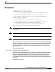
Preface Organization Organization This publication is organized as follows: Chapter/Appendix Description Chapter 1, Product Overview Describes the physical properties and provides a functional overview of the AVS 3120. Chapter 2, Preparing for Installation Describes safety considerations and provides an overview of the installation and procedures you should perform before the actual installation.
Preface Conventions Conventions This publication uses the following conventions: • Bold text indicates a command in a paragraph. • Courier text • Courier bold text • Italic text indicates the first occurrence of a new term, book title, and emphasized text. indicates text that appears in a command line, including the CLI prompt. indicates commands and text you enter in a command line. Lists use the following conventions: 1. A numbered list indicates that the order of the list items is important.
Preface Conventions Varoitus TÄRKEITÄ TURVALLISUUSOHJEITA Tämä varoitusmerkki merkitsee vaaraa. Tilanne voi aiheuttaa ruumiillisia vammoja. Ennen kuin käsittelet laitteistoa, huomioi sähköpiirien käsittelemiseen liittyvät riskit ja tutustu onnettomuuksien yleisiin ehkäisytapoihin. Turvallisuusvaroitusten käännökset löytyvät laitteen mukana toimitettujen käännettyjen turvallisuusvaroitusten joukosta varoitusten lopussa näkyvien lausuntonumeroiden avulla.
Preface Conventions Aviso INSTRUÇÕES IMPORTANTES DE SEGURANÇA Este símbolo de aviso significa perigo. Você está em uma situação que poderá ser causadora de lesões corporais. Antes de iniciar a utilização de qualquer equipamento, tenha conhecimento dos perigos envolvidos no manuseio de circuitos elétricos e familiarize-se com as práticas habituais de prevenção de acidentes.
Preface Conventions Aviso INSTRUÇÕES IMPORTANTES DE SEGURANÇA Este símbolo de aviso significa perigo. Você se encontra em uma situação em que há risco de lesões corporais. Antes de trabalhar com qualquer equipamento, esteja ciente dos riscos que envolvem os circuitos elétricos e familiarize-se com as práticas padrão de prevenção de acidentes. Use o número da declaração fornecido ao final de cada aviso para localizar sua tradução nos avisos de segurança traduzidos que acompanham o dispositivo.
Preface Conventions Cisco AVS 3120 Application Velocity System Hardware Installation Guide OL-11805-01 xiii
Preface Obtaining Documentation Obtaining Documentation Cisco documentation and additional literature are available on Cisco.com. This section explains the product documentation resources that Cisco offers. Cisco.com You can access the most current Cisco documentation at this URL: http://www.cisco.com/techsupport You can access the Cisco website at this URL: http://www.cisco.com You can access international Cisco websites at this URL: http://www.cisco.com/public/countries_languages.
Preface Documentation Feedback The Product Documentation DVD is created and released regularly. DVDs are available singly or by subscription. Registered Cisco.com users can order a Product Documentation DVD (product number DOC-DOCDVD= or DOC-DOCDVD=SUB) from Cisco Marketplace at the Product Documentation Store at this URL: http://www.cisco.com/go/marketplace/docstore Ordering Documentation You must be a registered Cisco.com user to access Cisco Marketplace.
Preface Product Alerts and Field Notices Reporting Security Problems in Cisco Products Cisco is committed to delivering secure products. We test our products internally before we release them, and we strive to correct all vulnerabilities quickly. If you think that you have identified a vulnerability in a Cisco product, contact PSIRT: • For emergencies only — security-alert@cisco.
Preface Obtaining Technical Assistance Obtaining Technical Assistance Cisco Technical Support provides 24-hour-a-day award-winning technical assistance. The Cisco Technical Support & Documentation website on Cisco.com features extensive online support resources. In addition, if you have a valid Cisco service contract, Cisco Technical Assistance Center (TAC) engineers provide telephone support. If you do not have a valid Cisco service contract, contact your reseller.
Preface Obtaining Additional Publications and Information Submitting a Service Request Using the online TAC Service Request Tool is the fastest way to open S3 and S4 service requests. (S3 and S4 service requests are those in which your network is minimally impaired or for which you require product information.) After you describe your situation, the TAC Service Request Tool provides recommended solutions.
Preface Obtaining Additional Publications and Information • The Cisco Product Quick Reference Guide is a handy, compact reference tool that includes brief product overviews, key features, sample part numbers, and abbreviated technical specifications for many Cisco products that are sold through channel partners. It is updated twice a year and includes the latest Cisco channel product offerings. To order and find out more about the Cisco Product Quick Reference Guide, go to this URL: http://www.cisco.
Preface Obtaining Additional Publications and Information Cisco AVS 3120 Application Velocity System Hardware Installation Guide xx OL-11805-01
C H A P T E R 1 Product Overview This chapter provides a basic functional overview of the Cisco AVS 3120 Application Velocity System and describes the hardware, major components, and front and rear panel indicators and controls.
Chapter 1 Product Overview System Hardware Features System Hardware Features The AVS 3120 is designed for AC-input power and has a single AC-input power supply. The AVS 3120 includes the following: • An integrated Ethernet controller that provides an interface for connecting to 10-Mbps, 100-Mbps, or 1000-Mbps networks. • Four 10BASE-T/100BASE-TX/1000BASE-TX Ethernet ports with RJ-45 receptacles. The Ethernet ports support autonegotiate, full-duplex, or half-duplex operation on an Ethernet LAN.
Chapter 1 Product Overview Ports and Connectors Rear Panel Features The rear panel contains the AC power receptacle, power switch, Ethernet connectors, and the console/serial connector. Figure 1-2 illustrates the rear panel ports and connectors. Rear Panel View 3 2 1 5 4 6 7 USB2 USB1 CONSOLE MGMT FLASH FL A SH S ST AT U LINK SPD LINK SPD LINK SPD LINK SPD 2 3 4 1 PO W ER AUX 153107 Figure 1-2 9 11 12 8 10 1 USB ports (not supported) 7 Power indicator. Off indicates no power.
Chapter 1 Product Overview Ports and Connectors Ethernet Connectors The AVS 3120 has four integrated 10/100/1000–megabit-per-second (Mbps) Ethernet connectors. The Ethernet controller provides an interface for connecting to 10-Mbps, 100-Mbps, or 1000-Mbps networks and supports autonegotiate, full-duplex, or half-duplex operation on an Ethernet LAN. To access an Ethernet port, connect a Category 3, 4, or 5 unshielded twisted-pair (UTP) cable to one of the RJ-45 connectors on the back of the chassis.
Chapter 1 Product Overview Ports and Connectors 10/100/1000 Port Pinouts Pin Label 1 TP0+ 2 TP0- 3 TP1+ 4 TP2+ 5 TP2- 6 TP1- 7 TP3+ 8 TP3- 1 2 3 4 5 6 7 8 60915 Figure 1-4 RJ-45 Cables Cisco products use the following types of RJ-45 cables: • Straight-through • Cross-over • Rolled (console) To identify the RJ-45 cable type, hold the two ends of the cable next to each other so that you can see the colored wires inside the ends, as shown in Figure 1-5.
Chapter 1 Product Overview Ports and Connectors Console Port The AVS 3120 has one serial port located on the rear panel that operates as the console port. The integrated serial port uses a RJ-45 connector. Figure 1-6 shows the pin number assignments for the port. Refer to Table 1-2 for the console port connector pinouts.
Chapter 1 Product Overview Ports and Connectors RJ-45 to DB-9 or DB-25 Adapter Table 1-4 lists the cable pinouts for the RJ-45 to DB-9 or DB-25 adapter. The DB-9 adapter is used to connect a rolled RJ-45 cable to the console serial port. The DB-9 or DB-25 adapter is used to connect the other end of the rolled RJ-45 cable to a PC or terminal serial port.
Chapter 1 Product Overview Ports and Connectors Cisco AVS 3120 Application Velocity System Hardware Installation Guide 1-8 OL-11805-01
C H A P T E R 2 Preparing for Installation This chapter contains important safety information that you should review before working with the AVS 3120. Use the following guidelines to ensure your own personal safety and to help protect your AVS 3120 from potential damage. Note Read the Regulatory Compliance and Safety Information for the Cisco AVS 3120 Application Velocity System document before you prepare the AVS 3120 for installation.
Chapter 2 Preparing for Installation Safety Note The English warnings in this document are followed by a statement number. To see the translations of a warning into other languages, look up its statement number in the Regulatory Compliance and Safety Information for the Cisco AVS 3120 Application Velocity System document that shipped with your appliance.
Chapter 2 Preparing for Installation Safety Warning This equipment is intended to be grounded to comply with emission and immunity requirements. Ensure that the switch functional ground lug is connected to earth ground during normal use.
Chapter 2 Preparing for Installation Safety General Precautions Observe the following general precautions when using and working with your AVS 3120: • Keep your AVS 3120 components away from radiators and heat sources, and do not block cooling vents. • Do not spill food or liquids on your AVS 3120 components, and never operate the product in a wet environment. If the AVS 3120 gets wet, see Chapter 4, “Troubleshooting the AVS 3120 Hardware” or contact the Cisco Technical Assistance Center.
Chapter 2 Preparing for Installation Safety • Use the correct external power source. Operate the product only from the type of power source indicated on the electrical ratings label. If you are not sure of the type of power source required, consult the Cisco Technical Assistance Center or a local power company. • Use approved power cable(s) only. You have been provided with a power cable for your AVS 3120 that is intended for its use (approved for use in your country, based on the shipping location).
Chapter 2 Preparing for Installation Preparing Your Site for Installation Figure 2-1 Chassis ESD Wrist Strap Ground Example 24304 Copper foil 100 Mbps Link PIX-515 DO NOT INSTALL INTERFACE CARDS WITH POWER APPLIED FDX 10/100 ETHERNET 0/0 Step 4 Caution 100 Mbps Link FAILOVER FDX 10/100 ETHERNET 0/0 CONSOLE Connect the work surface to the chassis using a grounding cable and alligator clip. Always follow ESD-prevention procedures when removing, replacing, or repairing components.
Chapter 2 Preparing for Installation Preparing Your Site for Installation Environmental Requirements When planning your site layout and equipment locations, remember the precautions described in this section to help avoid equipment failures and reduce the possibility of environmentally caused shutdowns. If you are experiencing shutdowns or unusually high errors with your existing equipment, these precautions will help you isolate the cause of failures and prevent future problems.
Chapter 2 Preparing for Installation Preparing Your Site for Installation Creating a Safe Environment Follow these guidelines to create a safe operating environment: • Keep tools and chassis components off of the floor and away from foot traffic. • Clear the area of possible hazards, such as moist floors, ungrounded power extension cables, and missing safety grounds.
Chapter 2 Preparing for Installation Precautions for Rack-Mounting Precautions for Rack-Mounting Warning Note To prevent bodily injury when mounting or servicing this unit in a rack, you must take special precautions to ensure that the system remains stable. The following guidelines are provided to ensure your safety: • This unit should be mounted at the bottom of the rack if it is the only unit in the rack.
Chapter 2 Preparing for Installation Precautions for Products with Modems, Telecommunications, or Local Area Network Options • Baffles can help to isolate exhaust air from intake air, which also helps to draw cooling air through the chassis. The best placement of the baffles depends on the airflow patterns in the rack. Experiment with different arrangements to position the baffles effectively.
C H A P T E R 3 Installing the AVS 3120 This chapter explains how to install the AVS 3120 in an equipment rack, or on a table or workbench. This chapter also provides instructions for connecting cables, AC power, and for booting the AVS 3120. Warning Read the installation instructions before connecting the system to the power source.
Chapter 3 Installing the AVS 3120 Unpacking and Inspecting the AVS 3120 Unpacking and Inspecting the AVS 3120 The AVS 3120 shipment contains the following items: • One RJ-45 to female 25-pin sub-d connector • One RJ-45 to female 9-pin sub-d connector • One RJ-45 console cable • Two 6-ft Ethernet cables • One rack mounting kit—two metal brackets and screws • Four rubber feet • Cisco Product Documentation CD-ROM and Warranty Package • Cisco AVS 3120 Application Velocity System Hardware Insta
Chapter 3 Installing the AVS 3120 Installing Your AVS 3120 Warning To prevent bodily injury when mounting or servicing this unit in a rack, you must take special precautions to ensure that the system remains stable. The following guidelines are provided to ensure your safety: • This unit should be mounted at the bottom of the rack if it is the only unit in the rack.
Chapter 3 Installing the AVS 3120 Installing Your AVS 3120 Figure 3-1 Attaching the Brackets to the Sides of the AVS 3120 Cisco AVS 31 20 series tion Ve lo Applica city Sy 143771 stem Note The top hole on the left bracket is a banana jack that you can use for ESD grounding purposes when you are servicing the system. You can use the two threaded holes to mount a ground lug to ground the chassis. 2.
Chapter 3 Installing the AVS 3120 Installing Your AVS 3120 Figure 3-2 Installing the AVS 3120 in a Two-Post Rack POWER STATUS Cisco AVS 312 Applicati 0 ser on Velo ies city Syst em 143772 FLASH To remove the appliance from the rack, remove the screws that attach the appliance to the rack, and then remove the appliance.
Chapter 3 Installing the AVS 3120 Installing Your AVS 3120 Connecting Cables Warning Do not work on the system or connect or disconnect cables during periods of lightning activity. Statement 1001 To connect network and console cables to your AVS 3120: For network connections, connect a Category 3, 4, or 5 unshielded twisted-pair (UTP) cable to the Ethernet port 1 connector on the AVS 3120 back panel (Figure 3-3). Ethernet port 1 is for management console connectivity. Note that in software version: 1.
Chapter 3 Installing the AVS 3120 Connecting AC Power Figure 3-4 Console Connection CONSOLE FLASH FL A SH PO W ER ST AT U S AUX Console port (RJ-45) Computer serial port DB-9 or DB-25 114418 RJ-45 to DB-9 or DB-25 serial cable (null-modem) Connecting AC Power Warning This equipment must be grounded. Never defeat the ground conductor or operate the equipment in the absence of a suitably installed ground conductor.
Chapter 3 Installing the AVS 3120 Booting the AVS 3120 5. Power up all externally-connected devices. 6. Switch on the power switch on the rear of the AVS 3120.
Chapter 3 Installing the AVS 3120 Establishing a Serial Console Connection Establishing a Serial Console Connection Before you can configure the AVS 3120 by using the command line interface (CLI), you must establish a serial console connection to it. This requires a PC, a DB-9 to RJ-45 adapter (provided), an RJ-45 180/rollover cable (provided), and terminal emulation communication software (Hyper Terminal or equivalent). You may also use a serial concentrator connection, if desired.
Chapter 3 Installing the AVS 3120 Configuring Network Settings Configuring Network Settings After you have installed the AVS 3120, you must configure the basic network settings by using the set command in the CLI from a console connection. After the basic network settings have been configured, you can perform additional CLI configuration through the network by using an SSH connection.
Chapter 3 Installing the AVS 3120 Configuring Network Settings You can view the DNS settings by using the show dns command: velocity>show dns PRIMARY NAMESERVER 10.68.226.120 SECONDARY NAMESERVER 10.68.226.121 Step 5 Configure the local time zone with the set date tz command: velocity>set date tz timezone where: is the local city/time zone name, such as America/New_York. To see a list of available city/time zone names, use the command show timezone all. The default time zone is America/Tijuana.
Chapter 3 Installing the AVS 3120 Setting the Time Step 8 We also recommend that you change the account password from its default. To do this, use the edit admin command: velocity>edit admin current-name fgn new-password password where: password is the new password for the fgn account. For more details about using the CLI and the Management Console, refer to the Cisco Application Velocity System User Guide.
Chapter 3 Installing the AVS 3120 Checking the Front Panel LEDs Checking the Front Panel LEDs When the AVS 3120 is up and operational, observe the front panel LEDs to monitor the AVS 3120 operating status. Figure 3-5 shows the location of front panel LEDs, and Table 3-1 describes their function.
Chapter 3 Installing the AVS 3120 Removing or Replacing an AVS 3120 Removing or Replacing an AVS 3120 Warning Before working on a system that has an on/off switch, turn OFF the power and unplug the power cord. Statement 1 Warning Ultimate disposal of this product should be handled according to all national laws and regulations. Statement 1040 To physically remove an AVS 3120 from your network follow these steps: 1. Login to the shell as the root user and execute the poweroff command. To do this: a.
C H A P T E R 4 Troubleshooting the AVS 3120 Hardware If your AVS 3120 is not working as expected, begin troubleshooting by using the procedures in this chapter. This chapter guides you through some initial checks and procedures that can solve basic AVS 3120 problems. This chapter contains the following major sections: • Checking the Basics, page 4-1 • Checking Connections, page 4-2 Checking the Basics To solve some basic AVS 3120 problems, follow these steps: 1.
Chapter 4 Troubleshooting the AVS 3120 Hardware Checking Connections 4. Did the AVS 3120 complete the boot routine? – Yes. The AVS 3120 configuration information was correct. – No. Call your service representative. Refer to the “Obtaining Technical Assistance” section on page xvii. Checking Connections Loose, incorrect, or improperly connected cables are the most likely source of problems for the AVS 3120 or other external equipment. A quick check of all cable connections can solve most problems.
C H A P T E R 5 Maintaining Your AVS 3120 Proper use of preventive maintenance procedures can ensure that the AVS 3120 operates properly and can minimize the need for time-consuming service procedures. This chapter contains maintenance procedures that you should perform regularly.
Chapter 5 Maintaining Your AVS 3120 Maintaining Your Site Environment Temperature Temperature extremes can cause a variety of problems, including premature aging and failure of chips or mechanical failure of devices. Extreme temperature fluctuations can cause chips to become loose in their sockets. To minimize the negative effects of temperature on AVS 3120 performance, follow these guidelines: • Ensure that the AVS 3120 operates in an environment no colder than 32°F (0°C) or hotter than 104°F (40°C).
Chapter 5 Maintaining Your AVS 3120 Maintaining Your Site Environment Dust and Particles A clean operating environment can greatly negate the effects of dust and other particles, which act as insulators and interfere with the operation of mechanical components. Also, in addition to regular cleaning, follow these guidelines to deter contamination of the AVS 3120 equipment: • Do not permit smoking anywhere near the AVS 3120. • Do not permit food or drink near the AVS 3120.
Chapter 5 Maintaining Your AVS 3120 Maintaining Your Site Environment To reduce the possibility of EMI and RFI, follow these guidelines: • Operate the AVS 3120 only with its cover installed. • Ensure that the screws on all peripheral cable connectors are securely fastened to their corresponding connectors on the back of the AVS 3120. • Always use shielded cables with metal connector shells for attaching peripherals to the AVS 3120.
Chapter 5 Maintaining Your AVS 3120 Using Power Protection Devices Using Power Protection Devices A number of devices are available that protect against power problems such as power surges, transients, and power failures. The following subsections describe some of these devices. Surge Protectors Surge protectors are available in a variety of types and usually provide a level of protection commensurate with the cost of the device.
Chapter 5 Maintaining Your AVS 3120 Using Power Protection Devices Cisco AVS 3120 Application Velocity System Hardware Installation Guide 5-6 OL-11805-01
A P P E N D I X A Specifications Table A-1 lists the specifications for the AVS 3120. Table A-1 AVS 3120 Specifications Dimensions and Weight Height 1.75 in. (4.45 cm) Width 17.5 in. (44.45 cm) Depth 14.5 in. (36.83 cm) Weight 20.0 lb (9.07 kg) Form factor 1 RU, standard 19-inch rack-mountable Expansion One chassis expansion slot (not used) Power Autoswitching 100 V to 240 V AC Frequency 47 to 63 Hz, single phase Operating current 3.
Appendix A Specifications Cisco AVS 3120 Application Velocity System Hardware Installation Guide A-2 OL-11085-01
A P P E N D I X B Open Source License Files Some components of this product may be covered under the open source license printed below. However, the Cisco warranty for the product shall remain in effect to its full extent and shall apply to the entire product. Apache License Apache License Version 2.0, January 2004 http://www.apache.org/licenses/ TERMS AND CONDITIONS FOR USE, REPRODUCTION, AND DISTRIBUTION 1. Definitions.
Appendix B Open Source License Files Apache License "Derivative Works" shall mean any work, whether in Source or Object form, that is based on (or derived from) the Work and for which the editorial revisions, annotations, elaborations, or other modifications represent, as a whole, an original work of authorship.
Appendix B Open Source License Files Apache License You may add Your own copyright statement to Your modifications and may provide additional or different license terms and conditions for use, reproduction, or distribution of Your modifications, or for any such Derivative Works as a whole, provided Your use, reproduction, and distribution of the Work otherwise complies with the conditions stated in this License. 5. Submission of Contributions.
Appendix B Open Source License Files Apache License Cisco AVS 3120 Application Velocity System Hardware Installation Guide B-4 OL-11805-01
I N D EX specifications A A-1 troubleshooting hardware issues AC power 2-8 unpacking and inspecting connecting to AVS 3120 cord, connecting 3-7 line conditioners 5-5 3-7 power source interruptions protection devices receptacle booting the AVS 3120 boot sequence 3-8 5-5 C 5-2 vii cable pinouts AVS 3120 booting 3-8 2-8 uninterruptible power supplies audience console port 3-8 RJ-45 boot sequence 3-8 configuring 3-10 connections 1-3 1-5 1-5 RJ-45 to DB-25 RJ-45 to DB-9 1-7 1-7
Index set ESD environment 3-10 compact flash working in compact flash indicator LED configuring the appliance 2-5 Ethernet interfaces 3-13 cabling requirements 3-10 connections Category 5 UTP cable cables 3-6 description power 3-7 Ethernet connectors troubleshooting indicators connections description 1-3 1-4 1-4 3-6 1-6 establishing connection F 3-9 1-3 front panel operating settings pinouts 3-6 1-4 Ethernet controller 4-2 console port location 1-4, 3-6 1-6 features
Index network, setting up 2-10 P precautions for rack-mounting 2-9 port connectors preparing for LAN options, precautions for modems, precautions for 2-10 required tools and equipment site preparation 2-10 2-10 1-3 connecting to system 3-7 power indicator LED 3-13 power protection devices 2-6 tools and equipment required two-post rack bracket instructions unpacking and inspecting 5-4 power supplies, using uninterruptible 2-10 power supply guidelines 3-3 5-4 5-5 power source inter
Index warnings and cautions with electricity regarding 2-1 batteries and explosion danger 2-4 sensors chassis, opening power supply guidelines 2-2 chassis, working on 2-8 serial port 2-3 disposal of unit 2-2 2-3 connection 3-9 explosion description 1-6 faceplates and cover panels, removing location pinouts 1-3 1-6 set command 2-3 failure to ground equipment 2-3 ground conductor, defeating 2-2, 2-7 installation area 3-10 site 2-7 instructions, reading environment, maintena