Cisco TelePresence System 3200 Assembly Guide Use & Care Guide Field-Replaceable Unit Guide July 28, 2008 Americas Headquarters Cisco Systems, Inc. 170 West Tasman Drive San Jose, CA 95134-1706 USA http://www.cisco.
THE SPECIFICATIONS AND INFORMATION REGARDING THE PRODUCTS IN THIS MANUAL ARE SUBJECT TO CHANGE WITHOUT NOTICE. ALL STATEMENTS, INFORMATION, AND RECOMMENDATIONS IN THIS MANUAL ARE BELIEVED TO BE ACCURATE BUT ARE PRESENTED WITHOUT WARRANTY OF ANY KIND, EXPRESS OR IMPLIED. USERS MUST TAKE FULL RESPONSIBILITY FOR THEIR APPLICATION OF ANY PRODUCTS.
Contents Preface ix Introduction i-ix Conventions i-ix Obtaining Documentation, Obtaining Support, and Security Guidelines Related Documentation CHAPTER 1 Overview i-x 1-1 Chapter Organization 1-1 Conventions and Terminology Tools and Equipment List CHAPTER 2 CHAPTER 3 1-3 1-3 Building the Display Assembly Parts List 2-1 2-1 Mounting and Leveling the Plasma Displays Parts List 5 Building the Display Shelf Assembly Parts List CHAPTER 4 CHAPTER 6 CHAPTER 7 8 9 6-1 6-1 7-1
Contents CHAPTER 10 First-Time Setup Parts List 10-1 10-1 Loading CTS Administration Software 10-1 Configuring an Alternate TFTP Server (Optional) Setting Up CTS Components 10-4 Setting Up the Displays 10-5 Setting Up the Cameras 10-6 Setting Up the Speakers 10-13 Setting Up the Microphones 10-13 Setting Up the Projector 10-14 Troubleshooting Presentation Devices Other Devices 10-18 CHAPTER 11 Use & Care Guide 11-1 Cleaning the Plasma displays 12 10-16 11-1 Maintaining the Tabletop CHAPTER
Contents Replacing a Microphone—Part Number CTS-MIC 12-12 Required Information, Tools, and Equipment 12-12 Removing and Replacing a First Row Microphone 12-12 Removing and Replacing a Second Row Microphone 12-13 Replacing a Light Fixture—Part Number CTS-LIGHT-FIXT Required Information, Tools, and Equipment 12-14 Replacement Bulbs 12-14 Replacing a Light Fixture 12-15 12-14 Replacing the Audio/Video Extension Unit—Part Number CTS-AV-EXP 12-15 Replacing the Auxiliary Control Unit—Part Number CTS-LIGHT-CT
Contents Carton 12 of 58: Camera Assembly Bracket, 69-1627-xx, CTS3K-STRUCTURE Carton 13 of 58: Brackets, 69-1632-xx, CTS3K-STRUCTURE A-6 A-6 Carton 14 of 58: Privacy Panel, Right Wing, 69-1628-xx, CTS3K-STRUCTURE A-6 Carton 15 of 58: Front Foot Stabilizer, 69-1624-xx, CST3K-STRUCTURE A-6 Carton 16 of 58: Front Foot Stabilizer, 69-1624-xx, CST3K-STRUCTURE A-7 Carton 17 of 58: Front Foot Stabilizer, 69-1624-xx, CST3K-STRUCTURE A-7 Carton 18 of 58: Display Structure Rear Feet, 69-1625-xx, CTS3K-ST
Contents Carton 48 of 58: Accessory Cabinet, Left, 69-1838-xx, CTS3K-M-TABLE-G2 Carton 49 of 58: Lighting Assembly, 69-1612-xx, CTS3K-LIGHT-STR A-16 A-16 Carton 50 of 58: Cisco TelePresence 3200 Structure—Addition to Standard CTS-3000, CTS32-STRUCTURE, 69-1854-01 A-17 Carton 51 of 58: Display Shelf Supports and Codec Tray, 69-1626-xx, CTS3K-STRUCTURE Carton 52 of 58: Tabletop Leg Base, 69-1620-xx, CTS3K-STRUCTURE A-18 Carton 53 of 58: Tabletop Leg Base, 69-1914-xx, CTS3K-STRUCTURE A-18 Carton 54 of
Contents Cisco TelePresence System 3200 viii OL-14521-01
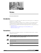
Preface Revised: July 28, 2008, OL-14521-01 Introduction The Cisco TelePresence 3200 Assembly Guide outlines the steps and best practices for assembling and installing the Cisco TelePresence 3200. This guide is intended primarily for installers of the Cisco TelePresence System 3200. Site planners, network administrators, and facility maintenance personnel may also find this document useful. This preface provides the following information for using this guide and for accessing other resources.
Preface Obtaining Documentation, Obtaining Support, and Security Guidelines Tip Means the information contains useful tips. Obtaining Documentation, Obtaining Support, and Security Guidelines For information on obtaining documentation, submitting a service request, and gathering additional information, see the monthly What’s New in Cisco Product Documentation, which also lists all new and revised Cisco technical documentation, at: http://www.cisco.com/en/US/docs/general/whatsnew/whatsnew.
CH A P T E R 1 Overview Revised: July 28, 2008, OL-14521-01 Chapter Organization Chapter 1, “Overview” (this chapter) • Provides chapter organization and content of this document and an overview of the steps you perform to install a CTS-3200 system. Chapter 2, “Building the Display Assembly” • The steps for assembling the three Display structures, connecting them, and positioning them in the conference room are described in a series of illustrations.
Chapter 1 Overview Chapter Organization Chapter 7, “Building the Second Row Table Assembly” • This chapter describes how to build the second row table and is organized the same as Chapter 2. Chapter 8, “Assembling the Remaining Cisco TelePresence Elements” • This chapter is organized the same as Chapter 2. • Each element is described using one or more illustrations.
Chapter 1 Overview Conventions and Terminology Step 2 Install and connect the PDUs for the display and first row table assembly. See Step 1 through Step 3 in Chapter 9, “Routing Power and Signal Cables” to install the PDUs and Step 4 in Chapter 9, “Routing Power and Signal Cables” to connect the cables. Step 3 Connect the projector to the projector mounting bracket and connect the projector and bracket to the table assembly.
Chapter 1 Overview Tools and Equipment List • Large Phillips screwdriver • Tin snips* • Pallet jack or hand cart (for moving component boxes to installation site)* • Safety gloves* • Safety glasses* • Box cutters* Cisco TelePresence System 3200 Structure, Accessory, and Adjustment Assembly: • Tip Power screwdriver with 3, 4, 5, and 6 mm (standard or round) Allen bits, or standard 3, 4, 5, and 6 mm Allen wrenches A round-head Allen bit can work at an angle instead of just straight out, a he
CH A P T E R 2 Building the Display Assembly Revised: July 28, 2008, OL-14521-01 Parts List Key Part Description Part Number Qty Ctn 1 Display structure 700-23358-xx 3 35, 36, 37 2 Rear foot stabilizer 700-23360-xx Kit# 69-1625-xx 6 18 3 Front foot stabilizer 700-23359-xx Kit # 69-1624-xx 6 15, 16, 17 4 Leveling foot 51-4540-xx Kit # 69-1654-xx 12 1 5 Display shelf support left 700-23339-xx Kit # 69-1626-xx 51 45 6 Display shelf support right 700-23340-xx Kit # 69-1626-01
Chapter 2 Building the Display Assembly Parts List Caution The display structures are unstable during assembly. Use caution, and support all structures as required. Warning Only trained and qualified personnel should be allowed to install, replace, or service this equipment. Note The directions left and right refer to the assembly as you face the Plasma displays. Note Before you start to build the structure, make sure that the floor in the installation room is level.
Chapter 2 Building the Display Assembly Parts List Step 2 Note Attach the Codec Safety trays to the Front Foot stabilizers. If you ordered a Presentation Codec, attach the larger tray that comes with the Presentation Codec package, part no. 700-25301-01, in the center display. Refer to the Cisco TelePresence Hardware Options and Upgrade Guide for more information.
Chapter 2 Building the Display Assembly Parts List Step 3 Attach the Rear and Front Foot stabilizers to the Display structures.
Chapter 2 Building the Display Assembly Parts List Step 4 Attach the left and right Display Shelf supports to each Display structure.
Chapter 2 Building the Display Assembly Parts List Step 5 Attach the Display Tilt brackets to each Display structure. Figure 2-5 Display Tilt brackets 7 1 12 13 201104 7 Note Do not tighten the Display Tilt brackets. You will need to adjust them to level the Plasma displays in Chapter 3, “Mounting and Leveling the Plasma Displays.
Chapter 2 Building the Display Assembly Parts List Step 6 Attach the Camera Assembly bracket to the center Display structure, making sure that this structure uses the larger codec tray. Figure 2-6 Camera Assembly bracket 13 9 13 201105 1 Note The Camera Assembly bracket attaches to the center Display structure.
Chapter 2 Building the Display Assembly Parts List Step 7 Attach the upper and lower Support crossbars to the left and right Display structures.
Chapter 2 Building the Display Assembly Parts List Step 8 Figure 2-8 Attach the upper and lower Support crossbars to the center Display structure. Upper and Lower Support crossbars 10 1 10 10 10 12 201108 11 Tip Use the screw holes nearest the ends of the Support crossbars.
Chapter 2 Building the Display Assembly Parts List Step 9 Figure 2-9 Position the three Display structures relative to the rear wall. Positioning the Display Structures 18 - 22” (45.7 cm - 55.
CH A P T E R 3 Mounting and Leveling the Plasma Displays Revised: July 28, 2008, OL-14521-01 Parts List Key Part Description Part Number Qty Ctn 1 65-inch high-definition display CTS-DISP-65GEN2 74-4881-xx 3 23, 24, 25 2 Black buffer strips 700-23981-xx 2 1 Display shelf section: left 95-9692-xx Kit # 74-5304-xx 1 58 Display shelf section: center 95-9694-xx Kit # 74-5306-xx 1 58 Display shelf section: right 95-9693-xx Kit # 74-5305-xx 1 58 M8 x 20 mm screws 48-2273-01 Warning
Chapter 3 Mounting and Leveling the Plasma Displays Parts List Step 1 Hang the left, center, and right Plasma displays on the Display structure crossbars. The left, center, and right Plasma displays 201109 Figure 3-1 Caution The edges of the Plasma displays are sharp and uncomfortable to lift with bare hands. Nonslip gloves are recommended. Note Make sure the Plasma display Leveling feet remain firmly seated on top of the Display shelf supports.
Chapter 3 Mounting and Leveling the Plasma Displays Parts List Step 2 Loosely attach the Display shelves to the Display shelf supports. Loosely Attach the Display shelves to the Display Shelf Supports 201111 Figure 3-2 Note The Display shelves are used in this chapter for leveling purposes only. See Chapter 5, “Building the Display Shelf Assembly” and use the M8 x 20 mm screws in the Accessory Kit to attach the display shelves.
Chapter 3 Mounting and Leveling the Plasma Displays Purpose of Leveling the Plasma displays Purpose of Leveling the Plasma displays The three Plasma displays act as windows allowing a three-way view into the remote Cisco TelePresence conference room. The Display shelf in front of each Plasma display acts as a visual bridge between the local and remote conference rooms.
Chapter 3 Mounting and Leveling the Plasma Displays Purpose of Leveling the Plasma displays Leveling Goals Leveling the Display shelves and the Plasma displays, and aligning the seams of the Display shelves with the edges of the Plasma displays ensure that images displayed from the remote conference room match the local conference room configuration. The leveling goals illustrated in Figure 3-4 through Figure 3-8 show how to use the leveling alignment points in Figure 3-3.
Chapter 3 Mounting and Leveling the Plasma Displays Purpose of Leveling the Plasma displays Step 5 The surface of the Display shelves should not obstruct any lines of resolution. Use the Plasma display Leveling feet to raise or lower the Plasma displays and make sure all lines of resolution can be seen when sitting at both the first and second conference tables.
Chapter 3 Mounting and Leveling the Plasma Displays Purpose of Leveling the Plasma displays Step 6 Tip Use the Plasma display Leveling feet to level the Plasma displays along the X axis. Use the Display tilt brackets to level the Plasma displays along the Y axis. You should level the center Plasma display first. Then align the left and right Plasma displays to the center display.
Chapter 3 Mounting and Leveling the Plasma Displays Purpose of Leveling the Plasma displays Step 7 Align the edges of Plasma displays The gap between Plasma displays should be uniformly even from the top edge of the Plasma display to the bottom edge. You should try to make the gap as small as possible.
Chapter 3 Mounting and Leveling the Plasma Displays Purpose of Leveling the Plasma displays Step 8 Align the seams of the Display shelves with the seams between Plasma displays. You may need to adjust the Plasma displays left to right so the seam created between the edges of two Plasma displays are aligned to the corresponding Display shelf seam.
Chapter 3 Mounting and Leveling the Plasma Displays Purpose of Leveling the Plasma displays Step 9 Apply the Black Buffer strips 201119 Figure 3-9 Complete the plasma display screen setup by applying the Black Buffer strips.
CH A P T E R 5 Building the Display Shelf Assembly Revised: July 28, 2008, OL-14521-01 Parts List Display Shelf, Type 1 Key Part Description Part Number Qty Ctn 1 Display shelf section: left 95-9692-xx Kit # 74-5304-xx 1 58 2 Display shelf section: center 95-9694-xx Kit # 74-5306-xx 1 58 3 Display shelf section: right 95-9693-xx Kit # 74-5305-xx 1 58 4 Not used 5 Left accessory cabinet attachment bracket 700-23336-xx 1 19 6 Right accessory cabinet attachment bracket 700-23337
Chapter 5 Building the Display Shelf Assembly Parts List Display Shelf, Type 1 Key Part Description Part Number Qty 3 Assembly Screen Supports No part number 2 4 M8 x 20 mm screws 48-2273-01 14 Caution Warning Caution Note Ctn Notes Located inside of assembly cabinet. These brackets are only required if you use a Type 1 projector screen, part number 800-28681-01.
Chapter 5 Building the Display Shelf Assembly Parts List Step 1 Figure 5-1 Attach the Display shelf hardware. Display shelf hardware 14 14 8 8 12 9 5 12 12 9 6 3 10 11 205467 1 Note The Right Accessory Cabinet attachment bracket (marked “6” in the illustration), has a central rectangular hole that differentiates it from the Left Accessory Cabinet attachment bracket.
Chapter 5 Building the Display Shelf Assembly Parts List Step 2 Figure 5-2 Attach the left Display shelf.
Chapter 5 Building the Display Shelf Assembly Parts List Step 3 Figure 5-3 Attach the center Display shelf Center Display shelf 13 13 Note 201149 2 Refer to Figure 5-1 to see the hardware used to attach the center Display shelf to the left Display shelf.
Chapter 5 Building the Display Shelf Assembly Parts List Step 4 Figure 5-4 Attach the right Display shelf. Right Display shelf 13 Note 13 201150 3 Refer to Figure 5-1 to see the hardware used to attach the right Display shelf to the center Display shelf.
Chapter 5 Building the Display Shelf Assembly Parts List Step 5 Attach the screen supports to the accessory cabinets and position, but do not attach, the cabinets to the left and right attachment brackets These screen supports are only required if you use a Type 1 projector screen, part number 800-28681-01. If your installation uses the projector screen with a product ID of CTS3K-SCREEN and a part number of 74-5416-01, do not install these brackets.
Chapter 5 Building the Display Shelf Assembly Parts List Cisco TelePresence System 3200 5-8 OL-14521-01
CH A P T E R 4 Building the Lighting Assembly Revised: July 28, 2008, OL-14521-01 Parts List Key Part Description Part Number Qty Ctn Notes 1 Lighting support brackets 700-23749-xx 6 49 2 Support struts 700-23752-xx 6 49 3 End structure brackets 700-23750-xx 4 49 4 Plastic diffuser panel: center 700-23745-xx 1 49 5 Plastic diffuser panel: ends 700-23746-xx 2 49 6 Plastic diffuser panel: top right 700-23747-xx 1 49 7 Plastic diffuser panel: top left 700-23748-xx 1 49
Chapter 4 Building the Lighting Assembly Parts List Key Part Description Part Number Qty Ctn Notes 23 Light “cup” bracket 700-23737-xx 2 43 24 5-foot center light fixture 74-4921-xx Kit # 95-8932-xx 3 31 25 4-foot side light fixture 74-5362-xx Kit # 95-8932-xx 2 30, See “Appendix B: Region- and 31 Country-Specific Equipment” for Europe- and Japan-specific lighting fixtures.
Chapter 4 Building the Lighting Assembly Parts List Step 1 Assemble the six Support struts and six Lighting Support brackets.
Chapter 4 Building the Lighting Assembly Parts List Step 2 Attach the left and right outer Support brackets (from Figure 4-1) to the horizontal bar on the left and right Display structures. Figure 4-2 Left and Right outer Support brackets (from Figure 4-1) 31 1 2 201126 31 Note Use any of the six brackets that you assembled in Step 1. There is no physical difference between the outer and inner Support brackets in Figure 4-1.
Chapter 4 Building the Lighting Assembly Parts List Step 3 Attach the four inner Support brackets to the Support crossbars. Figure 4-3 Four inner Support brackets (from Figure 4-1) 1 2 26 201127 31 Note Use any of the six brackets that you assembled in Step 1. There is no physical difference between the outer and inner Support brackets in Figure 4-1.
Chapter 4 Building the Lighting Assembly Parts List Step 4 Attach the four End structure brackets to the ends of the Support crossbars.
Chapter 4 Building the Lighting Assembly Parts List Step 5 Figure 4-5 Attach the three Reflector bottom trays to the Support brackets.
Chapter 4 Building the Lighting Assembly Parts List Step 6 Figure 4-6 Attach the two Reflector bottom spacers to join the three Reflector bottom trays.
Chapter 4 Building the Lighting Assembly Parts List Step 7 Figure 4-7 Attach the left and right (vertical) Reflector Bottom ends to the End Structure brackets and attach the compliance sticker to the left reflector bottom end.
Chapter 4 Building the Lighting Assembly Parts List Step 8 Figure 4-8 Attach the Light Cup bracket to the left and right (vertical) Reflector Bottom ends.
Chapter 4 Building the Lighting Assembly Parts List Step 9 Figure 4-9 Attach the three 5-foot Light fixtures inside the Reflector bottoms.
Chapter 4 Building the Lighting Assembly Parts List Step 10 Figure 4-10 Attach the left and right 4-foot Side Light fixtures to the left and right (vertical) Reflector Bottom ends. Left and Right 4-foot Side Light fixtures 25 201134 27 Note The power cords for the Side Light fixtures should extend from the top through the Light Cup bracket (Figure 4-8).
Chapter 4 Building the Lighting Assembly Parts List Step 11 Figure 4-11 Attach the two center Metal Trim panels.
Chapter 4 Building the Lighting Assembly Parts List Step 12 Figure 4-12 Attach the two side Metal Trim panels.
Chapter 4 Building the Lighting Assembly Parts List Step 13 Figure 4-13 Attach the center Plastic Diffuser panel.
Chapter 4 Building the Lighting Assembly Parts List Step 14 Figure 4-14 Attach the left and right plastic diffuser panels. Before fully tightening the screws, adjust the panels to the left or right to ensure that the spacing between the diffuser panels are even. Left and Right Plastic Diffuser panels 7 6 201138 31 Note The rounded corners of the left and right plastic diffuser panels point outward.
Chapter 4 Building the Lighting Assembly Parts List Step 15 Attach the four L-brackets to the two (vertical) end Plastic Diffuser panels.
Chapter 4 Building the Lighting Assembly Parts List Step 16 Figure 4-16 Attach the two (vertical) Plastic Diffuser panels to the End Structure brackets.
Chapter 4 Building the Lighting Assembly Parts List Step 17 Figure 4-17 Slide the Plastic Diffuser Panel brace between the end (vertical) Plastic Diffuser panel and the left and right Plastic Diffuser panels. Plastic Diffuser Panel brace 13 201202 29 Note If a diffuser becomes scratched, use a black felt-tip permanent marker to cover the imperfection.
Chapter 4 Building the Lighting Assembly Parts List Step 18 Figure 4-18 Attach the center Reflector top to the center Reflector bottom. Center Reflector top 17 13 201141 27 Note Do not tighten screws until completing Step 22.
Chapter 4 Building the Lighting Assembly Parts List Step 19 Figure 4-19 Attach the left and right Reflector tops to the left and right Reflector bottoms. Left and Right Reflector tops 18 32 18 14 201142 27 Note Do not tighten screws until completing Step 22.
Chapter 4 Building the Lighting Assembly Parts List Step 20 Figure 4-20 Join the left, center, and right Reflector tops with the left and right Reflector Transition pieces. Left and Right Reflector Transition pieces 21 18 28 17 20 201143 27 Note Do not tighten screws until completing Step 22.
Chapter 4 Building the Lighting Assembly Parts List Step 21 Figure 4-21 Attach the left and right (vertical) Reflector ends to the left and right (vertical) Reflector Bottom ends. Left and Right (vertical) Reflector ends 19 33 27 27 15 201144 19 Note Do not tighten screws until completing Step 22.
Chapter 4 Building the Lighting Assembly Parts List Step 22 Figure 4-22 Attach the left and right corner Reflector Transition pieces to the Reflector tops. Left and Right corner Reflector Transition pieces 28 22 27 18 18 201145 22 Note Tighten all screws from Figure 4-18 through Figure 4-22. The goal is to ensure the reflector pieces form a “seamless hood” around the lighting assembly.
Chapter 4 Building the Lighting Assembly Parts List Step 23 Figure 4-23 Attach the two Metal Trim panels to the L-brackets attached to the two (vertical) Plastic Diffuser panels. Two Metal Trim panels 11 5 11 201146 27 Note Install the codecs before you continue to the next chapter. See Step 5 through Step 8 in Chapter 8, “Assembling the Remaining Cisco TelePresence Elements” to install the codecs; then see Chapter 5, “Building the Display Shelf Assembly” to continue the installation.
Chapter 4 Building the Lighting Assembly Parts List Tip If required, use the white touch-up paint on the light reflectors to fix any minor cosmetic issues caused by assembly, shipping, or handling.
CH A P T E R 6 Building the First Row Table Assembly Revised: July 28, 2008, OL-14521-01 Parts List Key Part Description Part Number Qty Ctn 1 Tabletop leg base 800-28454-xx 3 5254 52 800-28628-xx (left) 1 2 Metal packaging brace 700-24275-xx 4 4143, 57 3 Molded foam bumper 800-28625-xx 4 4143, 57 4 Tabletop section: right wing 95-9690-xx Kit # 74-5302-xx 1 58 5 Tabletop section: Center right 95-9687-xx Kit # 74-5300-xx 1 58 6 Tabletop section: center 95-9686-xx Kit # 74-5
Chapter 6 Building the First Row Table Assembly Parts List Key Part Description Part Number 15 M4 x 12 mm flathead screws 48-1641-xx 16 Phillips head wood screws 17 Plate for left side table Part number to be provided 18 I/O blank: large 700-23806-xx 19 I/O blank: small 700-23807-xx 6 1 20 I/O modules: power/Ethernet 74-xxxx-xx 6 1 21 I/O Module Cover plate 700-23305-xx 22 10 m Cat6 Ethernet cable 37-0901-xx 6 1 23 3 m Jumper cord 37-0833-xx 9 1 24 M4 nuts 49-0326
Chapter 6 Building the First Row Table Assembly Parts List Note Warning Step 1 The directions left and right refer to the assembly as you face it from the front. Table legs are unstable until they are fully attached to the tabletop. Do not use unattached table legs as tabletop supports while you attach tabletop segments. They can fall and cause injury or damage. Cisco suggests you use the accessory cabinets to support and stabilize the table segments as you install them.
Chapter 6 Building the First Row Table Assembly Parts List Step 2 Figure 6-2 Assemble the four Molded foam bumpers and the four Table leg bases. Four Molded foam bumpers and the four Table leg bases Note The leg base with only one top right attachment bracket is the left most table leg (see Figure 6-12). The other three legs each have two attachment brackets.
Chapter 6 Building the First Row Table Assembly Parts List Step 3 Assemble the I/O modules for the outside left and outside right molded foam bumpers. The outside left and outside right molded foam bumpers only have one I/O module each. The inner molded foam bumpers have two (see Figure 6-4). Figure 6-3 Foam Bumper Assembly 21 18 25 22 23 24 204176 19 20 Note Steps for routing the Ethernet and power cables are in Chapter 9, “Routing Power and Signal Cables.
Chapter 6 Building the First Row Table Assembly Parts List Step 4 Assemble the I/O modules for the inner molded foam bumpers. Figure 6-4 Foam Bumper Assembly 25 21 19 20 204178 22 23 24 Note Steps for routing the Ethernet and power cables are in Chapter 9, “Routing Power and Signal Cables.” Note The flange on the I/O module cover place is wider on the bottom than on the top.
Chapter 6 Building the First Row Table Assembly Parts List Step 5 Figure 6-5 Attach the right wing tabletop section to the right Accessory Cabinet bracket.
Chapter 6 Building the First Row Table Assembly Parts List Step 6 Figure 6-6 Attach the right Table segment. a. Make sure you tighten the draw bolt evenly on both sides. b. While a draw bolt is being tightened, hold the table edges together to avoid damage to the draw bolt or the table segment. c. Tighten the draw bolt so the two table segments are connected snugly. d.
Chapter 6 Building the First Row Table Assembly Parts List Step 7 Figure 6-7 Attach the right most Table Leg.
Chapter 6 Building the First Row Table Assembly Parts List Step 8 Figure 6-8 Attach the center Table segment. a. Make sure you tighten the draw bolt evenly on both sides. b. While a draw bolt is being tightened, hold the table edges together to avoid damage to the draw bolt or the table segment. c. Tighten the draw bolts so the two table segments are connected snugly. d.
Chapter 6 Building the First Row Table Assembly Parts List Step 9 Figure 6-9 Attach the right center Table leg.
Chapter 6 Building the First Row Table Assembly Parts List Step 10 Figure 6-10 Attach the left Table segment. a. The draw bolts have two halves that screw into a center piece. b. While a draw bolt is being tightened, hold the table edges together to avoid damage to the draw bolt or the table segment. c. Tighten the draw bolts so the two table segments are connected snugly. d.
Chapter 6 Building the First Row Table Assembly Parts List Step 11 Figure 6-11 Attach the left center Table leg.
Chapter 6 Building the First Row Table Assembly Parts List Step 12 Figure 6-12 Attach the left most Table leg.
Chapter 6 Building the First Row Table Assembly Parts List Step 13 Attach one microphone to each table segment. There are three microphones for the first row table. The center microphone cable for the first row table must be seated in the cable channel on the underside of the center table segment in order to properly install the projector mounting bracket. You can use tape to secure it in place.
Chapter 6 Building the First Row Table Assembly Parts List Step 14 Figure 6-14 Attach the table door to the tabletop sections and attach the “please close” label to the underside of the table door.
Chapter 6 Building the First Row Table Assembly Parts List Step 15 Figure 6-15 Attach the center Privacy panel.
Chapter 6 Building the First Row Table Assembly Parts List Step 16 Figure 6-16 Attach the left Privacy panel.
Chapter 6 Building the First Row Table Assembly Parts List Step 17 Figure 6-17 Attach the right Privacy panel.
Chapter 6 Building the First Row Table Assembly Parts List Step 18 Attach the right wing Privacy panel.
CH A P T E R 7 Building the Second Row Table Assembly Revised: July 28, 2008, OL-14521-01 Parts List Key Part Description Part Number Qty Ctn 1 Tabletop leg base 800-28454-xx 7 5254 2 Metal packaging brace 700-24275-xx 7 4143, 57 3 Molded foam bumper 800-28625-xx 7 4143, 57 4 Gutter and privacy panel support bracket, 700-27280-xx type 1 2 50 5 Gutter and privacy panel support bracket, 700-27279-xx type 2 5 50 6 Gutter panel, section 1 800-31126-xx 1 50 7 Gutter panel, se
Chapter 7 Building the Second Row Table Assembly Parts List Key Part Description Part Number Qty Ctn 16 Tabletop: section 3 95-10097-01 Kit # 74-5601-01 1 26 17 Tabletop: section 4 95-10098-01 Kit # 74-5602-01 1 26 18 Tabletop: section 5 95-9994-01 Kit # 74-5562 2 26 19 Tabletop end, left (section 6) 95-10099-01 Kit # 74-5603-01 1 26 20 Tabletop end, right (section 7) 95-10100-01 Kit # 74-5604 1 26 21 Tabletop end brace 700-27413-xx 2 50 22 Privacy panel alignment brac
Chapter 7 Building the Second Row Table Assembly Parts List Key Part Description Part Number Qty Ctn 43 I/O blank: large 69-1830-01 2 1 44 I/O blank: small 700-23807-01 14 1 45 I/O modules: power/Ethernet 74-xxxx-xx 12 1 46 I/O Module Cover plate 700-23305-01 7 5054 47 Cat6 Ethernet cord 37-0887-02 (3M) 37-0901-01 (10M) 37-0965-01 (12M) 1 8 3 1 48 3 m Jumper cord 37-0833-01 9 1 49 M4 nuts 49-0326 20 1 50 M4 x 12 mm screws, black 48-2426-01 10 1 51 Microphone
Chapter 7 Building the Second Row Table Assembly Parts List Caution Note Warning Step 1 In order to prevent scratching the table tops, you should avoid putting any tools on the shelf surfaces. The directions left and right refer to the assembly as you face it from the front. Table legs are unstable until they are fully attached to the tabletop. Do not use unattached table legs as tabletop supports while you attach tabletop segments. They can fall and cause injury or damage.
Chapter 7 Building the Second Row Table Assembly Parts List Step 2 Figure 7-2 Assemble the seven Molded foam bumpers and the seven Table leg bases.
Chapter 7 Building the Second Row Table Assembly Parts List Step 3 Note Note the table layout. Each section is numbered as shown in Figure 7-3. Each cable gutter and privacy panel is different. The numbering for the cable gutters and privacy panels correspond to the numbering for the table top. Tip When you attach the support brackets, it can be helpful to turn the table leg upside-down.
Chapter 7 Building the Second Row Table Assembly Parts List Step 4 Gutter and Privacy Panel Support Brackets, Type 2 35 35 5 204102 Figure 7-4 Attach the second set of five support brackets to the table legs.
Chapter 7 Building the Second Row Table Assembly Parts List Step 5 Tip When you attach the support brackets, it can be helpful to turn the table leg upside-down. Section 1 Gutter Panel 204103 Figure 7-5 While one or more assistants keep the table legs steady, attach the Section 1 gutter panel to the Section 1 table legs.
Chapter 7 Building the Second Row Table Assembly Parts List Step 6 Section 2 Gutter Panel 204104 Figure 7-6 Attach the Section 2 gutter panel to the Section 2 table legs.
Chapter 7 Building the Second Row Table Assembly Parts List Step 7 Section 3 Gutter Panel 204105 Figure 7-7 Attach the Section 3 gutter panel to the Section 3 table legs.
Chapter 7 Building the Second Row Table Assembly Parts List Step 8 Note If you are building a Reduced Configuration table (four tabletops instead of six), continue to Step 11 after completing this step. Section 4 Gutter Panel 204106 Figure 7-8 Attach the Section 4 gutter panel to the Section 4 table legs.
Chapter 7 Building the Second Row Table Assembly Parts List Step 9 Section 5 (Left) Gutter Panels 204107 Figure 7-9 Attach the left Section 5 gutter panels to the remaining table legs.
Chapter 7 Building the Second Row Table Assembly Parts List Step 10 Section 5 (Right) Gutter Panels 204108 Figure 7-10 Attach the right Section 5 gutter panels to the remaining table legs.
Chapter 7 Building the Second Row Table Assembly Parts List Step 11 Assemble the I/O modules for the outside left and outside right molded foam bumpers. The outside left and outside right molded foam bumpers only have one I/O module each. The inner molded foam bumpers have two (see Figure 7-12).
Chapter 7 Building the Second Row Table Assembly Parts List Step 12 Note Assemble the I/O modules for the inner molded foam bumpers. The Ethernet cables are of different lengths. Attach the Ethernet cables to the I/O modules as follows: • Use the 12M cable, 37-0965-01, for the I/O modules between sections 6 and 5 • Use the 3M cable, 37-0887-02, for the I/O modules between sections 5 and 7 Note Steps for routing the Ethernet and power cables are in Chapter 9, “Routing Power and Signal Cables.
Chapter 7 Building the Second Row Table Assembly Parts List Step 13 Insert the second row PDUs in the lower cable gutters. Note Figure 7-13 You install the remaining PDUs and route the cables in Chapter 9, “Routing Power and Signal Cables.
Chapter 7 Building the Second Row Table Assembly Parts List Step 14 Note Before you attach the floating brackets, route the Ethernet and power cables in Chapter 9, “Routing Power and Signal Cables.” Note After you attach the brackets with the shoulder screws, move the brackets left and right to ensure that they can move freely. Floating Brackets, Type 1 204169 Figure 7-14 Attach the first set of floating brackets to the table assembly.
Chapter 7 Building the Second Row Table Assembly Parts List Step 15 Note Before you attach the floating brackets, route the power cables in Chapter 9, “Routing Power and Signal Cables.” Note After you attach the brackets with the shoulder screws, move the brackets left and right to ensure that they can move freely. Floating Brackets, Type 2 204170 Figure 7-15 Attach the second set of floating brackets to the table assembly.
Chapter 7 Building the Second Row Table Assembly Parts List Step 16 Privacy Panel Hanger 11 35 204109 Figure 7-16 Attach the privacy panel hangers to the table assembly.
Chapter 7 Building the Second Row Table Assembly Parts List Figure 7-17 Step 17 Place the section 1 and section 2 tabletops on the table assembly, insert the plastic spline in the slot of table section 1, and join the tables together, then insert and tighten the draw bolts evenly on each side until the tabletop sections are joined together. Note As you build the table tops, attempt to align the table feet with the table tops, and make sure that they table tops are supported on at least three sides.
Chapter 7 Building the Second Row Table Assembly Parts List Step 18 Figure 7-18 Place the Section 3 tabletop on the table assembly, insert the spline in the slot between the two tabletops, and use the draw bolts to join table tops 1 and 3 together.
Chapter 7 Building the Second Row Table Assembly Parts List Step 19 Note Figure 7-19 Join table section 4 to table section 2 using the draw bolts and spline. If you are building a Reduced Configuration table (four tabletops instead of six), continue to Step 22 after completing this step.
Chapter 7 Building the Second Row Table Assembly Parts List Step 20 Figure 7-20 Place the left tabletop section 5 on the table assembly and join it to the section 3 tabletop using the draw bolts and spline.
Chapter 7 Building the Second Row Table Assembly Parts List Step 21 Figure 7-21 Place the right tabletop section 5 on the table assembly and join it to the section 4 tabletop.
Chapter 7 Building the Second Row Table Assembly Parts List Step 22 Figure 7-22 Attach the left tabletop end to tabletop section 5 using the using the draw bolts, spline and alignment plate.
Chapter 7 Building the Second Row Table Assembly Parts List Step 23 Figure 7-23 Attach the Right tabletop end.
Chapter 7 Building the Second Row Table Assembly Parts List Step 24 Figure 7-24 Attach tabletop sections 1 and 2 to the table leg.
Chapter 7 Building the Second Row Table Assembly Parts List Step 25 Figure 7-25 Attach tabletop sections 1 and 3 to the table leg.
Chapter 7 Building the Second Row Table Assembly Parts List Step 26 Note Figure 7-26 Attach tabletop sections 2 and 4 to the table leg. If you are building a Reduced Configuration table (four tabletops instead of six), continue to Step 30 after completing this step.
Chapter 7 Building the Second Row Table Assembly Parts List Step 27 Tabletop Sections 3 and 5 and Table Leg 204121 Figure 7-27 Attach tabletop sections 3 and 5 to the table leg.
Chapter 7 Building the Second Row Table Assembly Parts List Step 28 Figure 7-28 Attach tabletop sections 4 and 5 to the table leg.
Chapter 7 Building the Second Row Table Assembly Parts List Step 29 Figure 7-29 Attach the reinforcement screws for the gutter panels.
Chapter 7 Building the Second Row Table Assembly Parts List Step 30 Figure 7-30 Attach the panel end brace to the table leg and left tabletop end and attach the table leg to the tabletop and tabletop end.
Chapter 7 Building the Second Row Table Assembly Parts List Step 31 Panel End Braces, Table Leg, Right Tabletop End and Table Section 5 35 21 204124 Figure 7-31 Attach the panel end brace to the table leg and right tabletop end, then attach the table leg to the tabletop and tabletop end. 35 35 Step 32 Figure 7-32 Attach the privacy panel alignment bracket to the underside of table section 1.
Chapter 7 Building the Second Row Table Assembly Parts List Step 33 Figure 7-33 Attach the privacy panel alignment bracket to the underside of table section 2. Section 2 Privacy Panel Alignment Bracket 23 204126 35 Step 34 Figure 7-34 Attach the privacy panel alignment bracket to the underside of table section 3.
Chapter 7 Building the Second Row Table Assembly Parts List Step 35 Note Figure 7-35 Attach the privacy panel alignment bracket to the underside of table section 4. If you are building a Reduced Configuration table (four tabletops instead of six), continue to Step 38 after completing this step. Section 4 Privacy Panel Alignment Bracket 25 204128 35 Step 36 Figure 7-36 Attach the privacy panel alignment bracket to the underside of left table section 5.
Chapter 7 Building the Second Row Table Assembly Parts List Step 37 Figure 7-37 Attach the privacy panel alignment bracket to the underside of right table section 5.
Chapter 7 Building the Second Row Table Assembly Parts List Step 38 Attach one microphone to each table segment and attach the microphone extension cords to the microphone cables. There are six microphones for the second row table. Note Steps for routing the microphone cables are in Chapter 9, “Routing Power and Signal Cables.” Tip Label each microphone cable where it exits from the table. You attach the microphones to the Audio/Video Expansion Unit in Chapter 9, “Routing Power and Signal Cables.
Chapter 7 Building the Second Row Table Assembly Parts List Step 39 Note Figure 7-39 Lift the privacy panel for table section 1 into position until it seats on the locating pins on the table assembly; then, use the plastic knob screws to loosely attach the privacy panel from below. Do not fully tighten the screws until you attach all privacy panels. You perform final spacing adjustments after you attach the last panel.
Chapter 7 Building the Second Row Table Assembly Parts List Step 40 Note Figure 7-40 Attach the privacy panel for section 2 to the table assembly. Align the panels so that the seam between privacy panels 1 and 2 is aligned with the table top seam for table tops 1 and 2.
Chapter 7 Building the Second Row Table Assembly Parts List Step 41 Figure 7-41 Attach the privacy panel for section 3 to the table assembly.
Chapter 7 Building the Second Row Table Assembly Parts List Step 42 Note Figure 7-42 Attach the privacy panel for section 4 to the table assembly. If you are building a Reduced Configuration table (four tabletops instead of six), continue to Step 45 after completing this step.
Chapter 7 Building the Second Row Table Assembly Parts List Step 43 Figure 7-43 Attach the privacy panel for left section 5 to the table assembly.
Chapter 7 Building the Second Row Table Assembly Parts List Step 44 Figure 7-44 Attach the privacy panel for right section 5 to the table assembly.
Chapter 7 Building the Second Row Table Assembly Parts List Step 45 Note Start with the seam between sections 1 and 2. The seam between the table tops should align with the seam between the privacy panels. Adjusting the Privacy Panels 204184 Figure 7-45 Adjust panels until all seams between the panels are even, then fully tighten the knob screws.
Chapter 7 Building the Second Row Table Assembly Parts List Step 46 Tip Install the cable cover so that it hides the cables that come out of the right side of the table section. Cable Cover 204173 Figure 7-46 Attach the cable cover for the right end privacy panel.
Chapter 7 Building the Second Row Table Assembly Parts List Step 47 Figure 7-47 Attach the privacy panel end pieces and the cable cover for the right end privacy panel.
Chapter 7 Building the Second Row Table Assembly Parts List Step 48 Figure 7-48 Position the second row table so that the trailing edge of the first row table is exactly 59 inches (150 cm) behind the leading edge of the second row table.
CH A P T E R 8 Assembling the Remaining Cisco TelePresence Elements Revised: July 28, 2008, OL-14521-01 Parts List Key Part Description Camera and Camera Assembly Part Number Qty Ctn Notes 1 Camera assembly 68-3277-xx 1 4 8 M8 x 20 mm pan head screws 48-2410-xx 4 1 7 M4 x 20mm cap screws 48-0654-xx 4 N/A These screws are included with the camera assembly and are used to attach the top and bottom hoods to the camera assembly.
Chapter 8 Assembling the Remaining Cisco TelePresence Elements Parts List Key Part Description Codec Assembly Part Number Qty Ctn 1 Primary codec 84-1321-xx 1 3 2 Secondary codec 68-2898-xx 2 5, 6, 40 3 Cable management bar 700-23449-xx 3 3, 5, 6, 40 4 Codec attachment brackets 700-23342-xx 6 13 5 M4 x 12 mm screws 48-1045-xx 20 1 6 M4 washers 49-0735-xx 20 1 Notes Speaker Assembly 1 Speaker 74-4740-xx 3 8 2 Speaker boards left and right 74-5544-xx 2 58 3 Spe
Chapter 8 Assembling the Remaining Cisco TelePresence Elements Parts List Key Part Description Part Number Qty Ctn 5 Horizontal bar 700-23960-xx 2 32 6 M4 x 20 mm screws 48-0654-xx 4 1 Notes Switch Bracket Note There are two additional brackets included with the accessory cabinet in Carton 33: 700-23338-xx and 700-23344-xx. These brackets attach the optional Ethernet switch to the left accessory cabinet.
Chapter 8 Assembling the Remaining Cisco TelePresence Elements Parts List Step 1 Place the assembly over the center display, then attach the Camera Assembly to the Camera Assembly bracket. For clarity, the display has been removed from the illustration in Figure 8-1. Note Figure 8-1 There are two foam pads on inside of the camera assembly.
Chapter 8 Assembling the Remaining Cisco TelePresence Elements Parts List Step 2 Attach the projector to the projector mounting bracket.
Chapter 8 Assembling the Remaining Cisco TelePresence Elements Parts List Step 3 Tip Figure 8-3 Attach the projector to the projector mounting bracket, and attach the assembly to the underside of the center Table segment. a. Make sure the center Microphone cable is routed securely within the cable channel on the underside of the center Table segment before attaching the Projector mounting bracket. a.
Chapter 8 Assembling the Remaining Cisco TelePresence Elements Parts List Step 4 Attach the VGA module to the center Table segment. The VGA module supports the VGA peripheral cable when not in use.
Chapter 8 Assembling the Remaining Cisco TelePresence Elements Parts List Step 5 Attach the Cable management bars to the three Codecs.
Chapter 8 Assembling the Remaining Cisco TelePresence Elements Parts List Step 6 Attach the Codec attachment brackets to the three Codecs.
Chapter 8 Assembling the Remaining Cisco TelePresence Elements Parts List Step 7 Note Attach the three codecs to the display structure codec safety trays. If you ordered a Presentation Codec with your TelePresence system, refer to the Cisco TelePresence Hardware Options and Upgrade Guide for instructions to install your presentation codec.
Chapter 8 Assembling the Remaining Cisco TelePresence Elements Parts List Step 8 Attach the Speaker board brackets and Leveling feet to the Speaker boards. The Speaker board brackets should angle towards the rear of the Display structure.
Chapter 8 Assembling the Remaining Cisco TelePresence Elements Parts List Step 9 Figure 8-9 Attach the Speaker boards to the Speaker board brackets on the underside of the Display shelves.
Chapter 8 Assembling the Remaining Cisco TelePresence Elements Parts List Step 10 Attach the Speakers to the Speaker boards.
Chapter 8 Assembling the Remaining Cisco TelePresence Elements Parts List Step 11 Attach the Projector screen to the Display shelves. Note Figure 8-11 Refer to your Cisco TelePresence Projector Screen Assembly manual for the exact procedures used to build and attach the projector screen. The Projector Screen Assembly manual is included in the projector screen carton.
Chapter 8 Assembling the Remaining Cisco TelePresence Elements Parts List Step 12 Audio/Video Expansion Unit and Bracket 204183 Figure 8-12 Attach the audio/video extension unit to its bracket.
Chapter 8 Assembling the Remaining Cisco TelePresence Elements Parts List Step 13 Audio/Video Extension Unit 35 204147 Figure 8-13 Attach the audio/video extension unit to the rear of the display assembly.
Chapter 8 Assembling the Remaining Cisco TelePresence Elements Parts List Step 14 Auxiliary Control Unit 35 1 204148 Figure 8-14 Attach the auxiliary control unit to its bracket using 5 mm screws; then, attach the unit and bracket to the rear of the display assembly.
Chapter 8 Assembling the Remaining Cisco TelePresence Elements Parts List Step 15 Assemble the Large Camera Target. When you slide the Camera target into the frame, make sure the target is centered in the frame between the vertical lines at the top and bottom of the target.
CH A P T E R 9 Routing Power and Signal Cables Revised: July 28, 2008, OL-14521-01 Parts List Key Part Description Part Number Qty Ctn 1 Power distribution units 74-4787-01 4 1 2 Speaker cable 37-0849-01 3 1 3 8 m DVI-to-VGA + audio cable 37-0848-01 1 1 4 6 m video cable 37-0854-01 2 1 5 3 m (black) Cat5 Ethernet cable 37-887-01 5 1 6 10 m Cat6 Ethernet cable, blue 37-0901-01 2 1 7 7 m power cord 37-xxxx-xx 1 8 3 m Jumper cord 37-0833-01 9 1 9 2 m Jumper cord
Chapter 9 Routing Power and Signal Cables Parts List Warning Caution Output receptacles cannot exceed 15A for any one receptacle. Correct routing of the various power cords to the appropriate PDU is critical for the safety and success of the Cisco TelePresence System 3200 assembly. Each PDU is routed to a different 20A circuit to prevent circuit overload when all the electrical components are properly installed.
Chapter 9 Routing Power and Signal Cables Parts List Step 1 Attach the two left Power Distribution Units (PDU) to the left Accessory cabinet. The accessory cabinets each have screw holes for two PDUs on one side wall and screw holes for one PDU on the other. When the cabinets are correctly oriented with each door opening out to the side, the right cabinet has the single-PDU side facing the rear wall, and the left cabinet has the double-PDU side facing the rear wall.
Chapter 9 Routing Power and Signal Cables Parts List Step 2 Attach the right PDU to the right Accessory cabinet. The accessory cabinets each have screw holes for two PDUs on one side wall and screw holes for one PDU on the other. When the cabinets are correctly oriented with each door opening out to the side, the right cabinet has the single-PDU side facing the rear wall, and the left cabinet has the double-PDU side facing the rear wall.
Chapter 9 Routing Power and Signal Cables Parts List Step 3 Figure 9-3 Attach the table assembly PDU attachment to the center privacy panel. Table assembly PDU attachment to the center Privacy panel 201184 1 Note The PDU power cable should extend from the right side.
Chapter 9 Routing Power and Signal Cables Parts List Step 4 Figure 9-4 Route the power cables for the first row table assembly. First Row Table Assembly Cable Routing CISCO IP PHONE 7970 TelePresence 1 4 GHI 7 PQRS 3 2 ABC 5 JKL 8 TUV 0 DEF 6 MNO 9 WXYZ # 8 Table Leg Power 9 Projector Power 201204 OPER Note The six jumper cords from the I/O modules in the table legs route to the center PDU. Tip Before plugging the Table leg jumper cords into the Table PDU, label each one.
Chapter 9 Routing Power and Signal Cables Parts List Step 5 Figure 9-5 Route the signal cables for the first row microphones, Cisco Unified IP Phone, and (if required) Ethernet connections in the first row table.
Chapter 9 Routing Power and Signal Cables Parts List Step 6 Microphone Cable Routing 204156 Figure 9-6 Route the second row microphone cables.
Chapter 9 Routing Power and Signal Cables Parts List Step 7 Ethernet Cable Routing 204157 Figure 9-7 If your installation uses wired Ethernet for the second row participants, attach the Ethernet cables to the modules in the foam bumpers and route the Ethernet cables.
Chapter 9 Routing Power and Signal Cables Parts List Step 8 Second Row Table Power Cable Routing 204172 Figure 9-8 Route the power cables for the second row table.
Chapter 9 Routing Power and Signal Cables Parts List Step 9 Note Figure 9-9 Connect the Cisco Unified IP Phone, VGA peripheral, and projector HD video cables. The VGA Peripheral cable is the free-hanging cable resting in the VGA module attached to the center Table segment.
Chapter 9 Routing Power and Signal Cables Parts List Step 10 Note If you have a Reduced Configuration for your second row table (four tabletops instead of six), use the same connections, but omit the connections (white connection 2 and red connection 3) for the two outer table tops. Cabling the Microphones 204162 Figure 9-10 Attach the microphone cables to the audio/video extension unit.
Chapter 9 Routing Power and Signal Cables Parts List Step 11 Figure 9-11 Attach and route the cables for the speakers. Cabling the Speakers Note Figure 9-11 displays the rear view of the Cisco TelePresence System 3200. Left and right are reversed. Tip Before plugging cables into the Codec, label each one. For example, Left Speaker, Center Speaker.
Chapter 9 Routing Power and Signal Cables Parts List Step 12 Figure 9-12 Connect the following cables: • Attach and route the power cables for the lighting assembly by connecting the lights to the auxiliary control unit. • Connect the serial cable between the projector and the auxiliary control unit. • Connect the Ethernet cables between the codec and the auxiliary control unit. • Connect the power cord for the auxiliary control unit to a wall outlet.
Chapter 9 Routing Power and Signal Cables Parts List Tip Step 13 Figure 9-13 Before plugging the Light fixture power cables into the unit, label each one. For example, 5’ Left light, 4’ Right light. Attach and route the power and signal cables for the plasma displays. Cabling the Plasma Display 201164 Signal Power Note Figure 9-13 displays the rear view of the Cisco TelePresence System 3200. Left and right are reversed. Tip Before you plug cables into a Codec or PDU, label each cable.
Chapter 9 Routing Power and Signal Cables Parts List Step 14 Cabling the Camera Assembly 14 15 5 10 15 RJ45 Power over Ethernet HDMI connector Note 204165 Figure 9-14 Attach and route the power-over-Ethernet and HD Video cables for the camera. The camera cluster can experience radio frequency interference issues if the camera Ethernet and HD Video cables are routed, bundled, or tied together.
Chapter 9 Routing Power and Signal Cables Parts List Step 15 Note Figure 9-15 Attach the cables between the codecs. If you ordered a Presentation Codec with your TelePresence system, refer to the Cisco TelePresence Hardware Options and Upgrade Guide for cabling instructions for the presentation codec.
Chapter 9 Routing Power and Signal Cables Parts List Note Step 16 Connect the power cables for the codecs. Cabling the Codecs Power 204167 Figure 9-16 Figure 9-15 displays the rear view of the Cisco TelePresence System 3200. Left and right are reversed.
Chapter 9 Routing Power and Signal Cables Parts List Step 17 Figure 9-17 (Optional) If your installation uses an optional external display or a document camera, install and route the cabling.
Chapter 9 Routing Power and Signal Cables Parts List Step 18 (Optional) If your installation uses an external display or a document camera with a presentation codec, install and route the cabling. Refer to the “Options for the Cisco TelePresence System 3200” chapter of the Cisco TelePresence Hardware Options and Upgrade Guide for more information about the presentation codec.
Chapter 9 Routing Power and Signal Cables Parts List Cisco TelePresence System 3200 OL-14521-01 9-21
Chapter 9 Routing Power and Signal Cables Parts List Cisco TelePresence System 3200 9-22 OL-14521-01
CH A P T E R 10 First-Time Setup Revised: February 6, 2009, OL-14521-01 After you have assembled the Cisco TelePresence System (CTS), you set up the individual system components (such as displays and cameras) using Hardware Setup, located under Troubleshooting in the CTS Administration software.
Chapter 10 First-Time Setup Loading CTS Administration Software Note Make sure that you power on all codecs within 30 seconds to avoid power on detection failure. After you turn on the codecs, the displays associated with each codec becomes active. CTS displays green check marks on all displays to show bootup progress. Bootup is complete when the system displays six check marks as shown in Figure 10-1.
Chapter 10 First-Time Setup Loading CTS Administration Software Figure 10-2 System IP Address Note Note If the IP address that displays is 192.168.100.2, the CTS-3200 could not contact the DHCP server or your system does not use DHCP. If your network does not use DHCP, navigate to Configuration > IP Settings, change the DHCP Enabled setting to No, and specify a static IP address, subnet mask, gateway and DNS server. Step 3 After successful bootup, the CTS Administration Software loads.
Chapter 10 First-Time Setup Configuring an Alternate TFTP Server (Optional) Step 6 Note From the Cisco IP telephone welcome page, press Next. The system reboots. The system might reboot several times during the initial startup process. Step 7 Open a browser on a computer that is connected to the network. Step 8 In the URL field, type the IP address that you obtained in Step 4 and press Enter. The browser launches Cisco TelePresence System Administration.
Chapter 10 First-Time Setup Setting Up CTS Components Step 1 Using the IP address displayed in the Cisco IP telephone welcome message, log in to the CTS Administration software. Step 2 From Troubleshooting, choose Hardware Setup to initially set up the components in the Cisco TelePresence system.
Chapter 10 First-Time Setup Setting Up CTS Components Troubleshooting Displays Use Table 10-1 to troubleshoot problems with the images on the displays. Table 10-1 Troubleshooting Chart for Display Problems Problem Cisco TelePresence 3000/3200 only Power-on test indicates the displays turn on in the wrong sequence. The normal power on sequence is the left, center, then right display screen. No image.
Chapter 10 First-Time Setup Setting Up CTS Components Attach the Camera Targets Two camera targets are provided with the Cisco TelePresence system: a large white target and a smaller target. You attach the large white target to the table prior to performing Auto Adjust (white balancing). Attach the large Camera target to the corresponding Table segment, with the clamps matching the counterbore feature under the table.
Chapter 10 First-Time Setup Setting Up CTS Components Figure 10-3 Camera Mounting Plate Left/right screws Rotation screws Lens 201205 Up/down screw Cisco TelePresence System 3200 10-8 OL-14521-01
Chapter 10 First-Time Setup Setting Up CTS Components Figure 10-4 Correct Camera Target Alignment—Center Display Red plus sign within black cross Note curved lines touching screen border 205764 Red lines Figure 10-5 Table edge Correct Camera Target Alignment—Right Display Red Vertical line Red plus sign within black cross 205765 Red lines Table edge Cisco TelePresence System 3200 OL-14521-01 10-9
Chapter 10 First-Time Setup Setting Up CTS Components Figure 10-6 Correct Camera Target Alignment—Left Display Red Vertical line Red plus sign within black cross 205766 Red lines • Click Hide Camera Target to remove the alignment images. • Click Done when you complete the adjustment. Table edge Show All Camera Targets • Click Show All Camera Targets to align each camera independent of the other cameras.
Chapter 10 First-Time Setup Setting Up CTS Components Figure 10-7 Attaching the Camera Hood Assembly 7 2 1 3 201203 7 Troubleshooting Cameras Use Table 10-2 to troubleshoot problems with cameras.
Chapter 10 First-Time Setup Setting Up CTS Components Table 10-2 Troubleshooting Chart for Camera Problems Problem Cisco TelePresence 3000/3200 only Camera image appears on the wrong display. Possible Cause Action Cables are plugged into the wrong connector ports. Check that the cables from each camera are plugged into the correct connector on its respective codec.
Chapter 10 First-Time Setup Setting Up CTS Components Setting Up the Speakers The speakers are set up correctly you can hear sound clearly from each one. You can choose whether you want to cycle through the speakers automatically or manually. • Click Speakers on the Hardware Setup window to select the speaker test. • Click Start to begin the speaker setup. • Click Cycle Through Speakers to have sound cycled automatically for 5 seconds on each speaker.
Chapter 10 First-Time Setup Setting Up CTS Components • Click Refresh Microphones Status (CTS-3200s only) to update the on/off status of all microphones. • Click Stop when setup is complete. Troubleshooting Microphones Use Table 10-4 to troubleshoot problems with microphones. Table 10-4 Troubleshooting Chart for Microphone Problems Problem Possible Cause Possible Solution Sound is muffled. Something near or on the microphone is distorting the sound. Move objects away from the microphone.
Chapter 10 First-Time Setup Setting Up CTS Components Step 1 Make sure that a serial cable is connected from your projector to the Serial output of the auxiliary control unit. See Chapter 9, “Routing Power and Signal Cables” for information about cabling your system with an Auxiliary Control Unit. Step 2 Start a test pattern display for the projector by completing the following steps: Step 3 a. Open a browser that is connected to the network. b.
Chapter 10 First-Time Setup Setting Up CTS Components Completing this step should center the image in the screen. If the image is not centered, adjust the image until the distance is equal from each table segment seam. e. Step 7 Tip Move the switch to the lock position. Aim the remote control at the lens of the projector. You can use the screen to reflect the signal back to the projector if you are sitting at the table. Leave the projector in this state.
Chapter 10 First-Time Setup Setting Up CTS Components Table 10-5 Troubleshooting Chart for Presentation Device Problems (continued) Problem Possible Cause Possible Solution Test pattern is not displayed. HD Video cable is not connected Check that the HD Video cable is to the projector or to the primary plugged into the projector and codec. into the correct connector on the primary codec.
Chapter 10 First-Time Setup Setting Up CTS Components Other Devices Use Other Devices to check the Auxiliary Control Unit, which controls the individual light units surrounding the displays in CTS conference rooms and enables the CTS to get more complete projector status information and to restores projector defaults. • Click Other Devices on the Hardware Setup window. • Click the Start radio button to access the Auxiliary Control Unit to begin testing. To end the test, click Stop.
CH A P T E R 11 Use & Care Guide Revised: July 28, 2008, OL-14521-01 Maintaining the Tabletop Cleaning your wood surfaces To avoid the build-up of dirt, dust all wood surfaces on a regular basis. This should be done with a soft, lint free cloth, slightly moistened with water only. Wipe lightly in the direction of the wood grain and dry immediately with another cloth. Remember to wipe lightly as dust is abrasive and can cause fine scratches.
Chapter 11 Use & Care Guide Cleaning the Camera lens Cleaning the Camera lens Caution Do not touch the camera after installation is completed. If you need to clean the camera lens, use a dry microfiber cloth. After cleaning, you will need to realign the camera. Maintaining the Projector Note Refer to the Projector User Guide included with your projector for maintenance issues such as cleaning the projector lens.
CH A P T E R 12 Field-Replaceable Unit Guide Revised: July 28, 2008, OL-14521-01 This chapter describes the steps you perform to replace the field-replaceable units (FRUs) for the Cisco TelePresence system and includes the following sections: • Powering On the System, page 12-1 • Replacing the Camera Cluster—Part Number CTS3K-CAM-CLST-G2, page 12-2 • Replacing a Plasma Display—Part Number CTS-DISP-65-GEN2, page 12-4 • Replacing a Speaker—Part Number CTS-LDSPKR, page 12-8 • Replacing a Codec Unit
Chapter 12 Field-Replaceable Unit Guide Replacing the Camera Cluster—Part Number CTS3K-CAM-CLST-G2 b. Step 2 Change the device MAC address to the MAC address for the new primary codec. The MAC address should be displayed on the codec. Power on the Cisco TelePresence 3200 by turning the power switches to the On position on the two left PDUs, single right PDU, and auxiliary control unit. Six check boxes display on the lower left corner of the center display screen.
Chapter 12 Field-Replaceable Unit Guide Replacing the Camera Cluster—Part Number CTS3K-CAM-CLST-G2 • Power screwdriver with 2.5, 3, and 6 mm (standard or round) Allen bits, or standard 2.5, 3, and 6 mm Allen wrenches • 0.
Chapter 12 Field-Replaceable Unit Guide Replacing a Plasma Display—Part Number CTS-DISP-65-GEN2 Step 7 Reattach the Ethernet and signal cables according to your temporary markings. Do not attach the camera hoods at this time. Step 8 Power on the system by completing the steps in the “Powering On the System” section on page 12-1. Step 9 Perform the camera adjustment procedure and, if required, refocus and realign the camera. See the “Setting Up the Cameras” section on page 10-6 for more information.
Chapter 12 Field-Replaceable Unit Guide Replacing a Plasma Display—Part Number CTS-DISP-65-GEN2 • Laptop computer attached to network • * Step ladder * Recommended for best results Removing Audio Components Caution Step 1 Caution Step 2 Take care not to mar or introduce smudges or dirt to the surface of the projector screen.
Chapter 12 Field-Replaceable Unit Guide Replacing a Plasma Display—Part Number CTS-DISP-65-GEN2 Removing the Camera Cluster If you are replacing the center Plasma display, you must remove the camera cluster. Refer to the previous section, Removing and Replacing the Camera Cluster for this procedure. Removing the Left Door The left tabletop door section must be removed to allow room to move the Plasma displays in and out of the work area.
Chapter 12 Field-Replaceable Unit Guide Replacing a Plasma Display—Part Number CTS-DISP-65-GEN2 Removing the Display Screen and Completing the Procedure Step 1 Detach the display screen’s signal cable from the correct codec unit. See Chapter 9, “Routing Power and Signal Cables” for cable locations and reference. Step 2 Detach the display screen’s power cable from the correct PDU. See Chapter 9, “Routing Power and Signal Cables” for cable locations and reference.
Chapter 12 Field-Replaceable Unit Guide Replacing a Speaker—Part Number CTS-LDSPKR Step 19 Perform the display adjustment procedure. See the “Setting Up the Displays” section on page 10-5 for more information. Step 20 If you moved the camera, complete the following steps: a. Perform the camera adjustment procedure and, if required, refocus and realign the camera. See the “Setting Up the Cameras” section on page 10-6 for more information. b. Attach the camera hood and lens hood.
Chapter 12 Field-Replaceable Unit Guide Replacing a Speaker—Part Number CTS-LDSPKR • Caution Step 2 The auxiliary control unit on the center display structure Make sure all system power is turned off before beginning this disassembly. Remove the Projector screen by performing one of the following actions: • If your projector screen is slightly recessed and uses black side trims, complete the following steps: a. Remove the side trims from the edges of the display.
Chapter 12 Replacing a Codec Unit—Part Number CTS-CODEC-PRI-G2 (Primary Codec) or CTS-CODEC-SEC (Secondary Codec) Field-Replaceable Unit Guide Replacing a Codec Unit—Part Number CTS-CODEC-PRI-G2 (Primary Codec) or CTS-CODEC-SEC (Secondary Codec) Required Information, Tools, and Equipment To remove and replace a codec unit for the Cisco TelePresence 3200, you need the following information, tools, and equipment: • Cisco TelePresence System Release 1.
Chapter 12 Field-Replaceable Unit Guide Replacing a Codec Unit—Part Number CTS-CODEC-PRI-G2 (Primary Codec) or CTS-CODEC-SEC (Secondary Codec) Step 6 Remove the codec from the Display structure. Step 7 Remove the L brackets from the codec. See Chapter 8, “Assembling the Remaining Cisco TelePresence Elements” for additional information. Step 8 Remove the cable management bar from the codec. Retain the bar and the screws.
Chapter 12 Field-Replaceable Unit Guide Replacing a Microphone—Part Number CTS-MIC Replacing a Microphone—Part Number CTS-MIC Required Information, Tools, and Equipment To remove and replace a microphone for the Cisco TelePresence 3200, you need the following information, tools, and equipment: • Cisco TelePresence System Release 1.4 Administrator’s Guide, OL-13676-03 • Power screwdriver with 2.5, 3, and 6 mm (standard or round) Allen bits, or standard 2.
Chapter 12 Field-Replaceable Unit Guide Replacing a Microphone—Part Number CTS-MIC Step 7 Pull the cable out through the hole and set the microphone aside. Note If you are replacing a microphone in the second row, you must also remove the privacy panel for that Step 8 Pull the replacement microphone cable through the hole in the tabletop. Step 9 From the underside of the tabletop, attach the microphone by screwing in the two screws.
Chapter 12 Field-Replaceable Unit Guide Replacing a Light Fixture—Part Number CTS-LIGHT-FIXT Step 8 Attach the privacy panels to the table sections. Note If required, adjust the privacy panel sections so that there is an equal amount of space between each section. Step 9 If required, replace the cable cover for the right end privacy panel as shown in Figure 7-46 and add cable ties to bundle the microphone cable with other cables.
Chapter 12 Field-Replaceable Unit Guide Replacing the Audio/Video Extension Unit—Part Number CTS-AV-EXP Replacing a Light Fixture Step 1 Note Power off the Auxiliary Control Unit by turning the power switch to the Off position. The Auxiliary Control Unit is located in the center of the display assembly. See Chapter 9, “Routing Power and Signal Cables” for more information. Step 2 Unplug the light fixture cord(s) from the Auxiliary Control Unit.
Chapter 12 Field-Replaceable Unit Guide Replacing the Auxiliary Control Unit—Part Number CTS-LIGHT-CTRL Caution Step 2 Make sure all system power is turned off before beginning this disassembly. Remove the cables from the audio/video extension unit. Label each cable with masking tape for identification as it is removed. See Chapter 9, “Routing Power and Signal Cables” for additional information.
Chapter 12 Field-Replaceable Unit Guide Replacing the Cisco Unified IP Phone—Part Number CP-7975G-CTS Step 5 Attach the cables to the new auxiliary control unit using the masking tape labels as a guide. Step 6 Power on the system by completing the steps in the “Powering On the System” section on page 12-1. Replacing the Cisco Unified IP Phone—Part Number CP-7975G-CTS Step 1 Open a browser on a computer connected to the network.
Chapter 12 Field-Replaceable Unit Guide Replacing the Projector—Part Number CTS-PRJTR-GEN1 Step 5 Remove the projector assembly by sliding the unit to the front until the projector mounting bracket disengages from the loosened mounting screws. Step 6 Loosen the screw that secures the lamp cover, then open the lamp cover. Access the cover through the cut-out rectangle on the projector mounting bracket. Step 7 Use the screwdriver to loosen the two screws that secure the lamp fixture in place.
Chapter 12 Field-Replaceable Unit Guide Replacing a PDU—Part Number CTS-PWR-PDU Step 10 Reattach the power cable to the projector. Step 11 Reattach the serial cable to the auxiliary control unit. Step 12 Power on the projector by turning on the power switch located on the back of the unit. Step 13 Perform first-time setup procedures for the projector by completing the steps in the “Setting Up the Projector” section on page 10-14.
Chapter 12 Field-Replaceable Unit Guide Replacing a Display Shelf Note If your administrator has changed the user name or password, enter those values. Step 10 Click Login. Step 11 Verify the status of the Cisco Unified Communications Manager (seen in the lower left portion of the window) is Enabled/Up. Step 12 Choose System Restart to perform a software reset. Refer to the Cisco TelePresence System Administrator's Guide for your software release for more information.
Chapter 12 Field-Replaceable Unit Guide Replacing a Display Shelf Be careful not to mar the screen when you perform this step. b. Use an open-ended wrench to loosen the feet on the bottom of the screen, and lower the screen. c. After you have created a gap of approximately 1/2 inch (1 centimeter) between the screen and the display shelf, detach the holes on the top screen from the locating pins on the underside of the display shelves and remove the screen.
Chapter 12 Field-Replaceable Unit Guide Replacing a First Row Table Top Section Tip Step 19 The projector screen comes with printed instructions that should assist you with replacing it. If you cannot find the instructions, reverse the order of removal to install it. Power on the system by completing the steps in the “Powering On the System” section on page 12-1. Replacing a First Row Table Top Section Complete these steps to replace a first row table top section.
Chapter 12 Field-Replaceable Unit Guide Replacing a First Row Table Top Section Note Make sure that the leg still supports both table top sections. Step 8 Remove the draw bolts between the table top sections on the side that you moved. See Chapter 6, “Building the First Row Table Assembly” for the location of the draw bolts. Step 9 If required, reposition the table leg so that it fully supports both table sections.
Chapter 12 Field-Replaceable Unit Guide Replacing a Second Row Table Top Section Replacing a Second Row Table Top Section Complete these steps to replace a second row table top section. Required Information, Tools, and Equipment To remove and replace a second row table top, you need the following tools: Tip • Medium and large Phillips screwdriver • 10 mm wrench A 10 mm open end ratcheting wrench is useful to loosen and tighten the draw bolts.
Chapter 12 Field-Replaceable Unit Guide Replacing a Second Row Table Top Section Step 6 If you are replacing the left or right tabletop end, remove the privacy panel end piece and panel end brace. See Figure 7-47 for the privacy panel end piece locations and Figure 7-30 for the panel end brace locations. Step 7 Remove the privacy panel hangers from the table legs that support the table top section to be replaced.
Chapter 12 Field-Replaceable Unit Guide Replacing a Second Row Table Top Section Step 20 Place the splines in the slots on the edge of the new table top section. Step 21 Press the table top sections together. Step 22 Insert the draw bolts and tighten them between the new table top section and the adjoining table top sections. See Chapter 7, “Building the Second Row Table Assembly” for the location of the draw bolts.
A P P E N D I X A Appendix A: Parts List Sorted by Carton Revised: July 28, 2008, OL-14521-01 Overview • Each table represents a separate carton. • Each carton may contain multiple parts. Some of these parts are grouped together in kits. Each kit is a smaller box contained within a larger carton. • If the kit box also contains boxes or bags, each one is identified with an ID number.
Appendix A Appendix A: Parts List Sorted by Carton Carton 1 of 58: Mechanical Accessory Kit, CTS3K-ACC-KIT, 53-2855-xx Sub-Kit ID Kit ID Number Number Part Number Part Description Qty Chapter Parts List Reference 78-17839-04 Regulatory Compliance and Safety Information 1 N/A 78-18735-01 Cisco TelePresence System 3200 Assembly, Use 1 & Care, and Field Replacement Unit Guide (pointer to online document) N/A 79-0087-02 ESD wrist strap 1 N/A 700-23825-03 Table hinge safety strap 1 Chapter
Appendix A Appendix A: Parts List Sorted by Carton Carton 2 of 58: Mechanical Accessory Kit, 53-2855-xx, CTS3K-ACC2-KIT Sub-Kit ID Kit ID Number Number Part Number Part Description 800-30442-0 1 73-11609-02 CTS-AV-EXP Cisco TelePresence Audio/Video Extension Unit 1 with mounting accessories Chapter 8 N/A1 48-2426-01 M8 x 12 mm screw, black 4 Chapter 7 CP-7975GCTS 68-3309-01 Cisco IP Phone 7975G 1 Chapter 7 N/A 69-1691-01 VGA Module 1 Chapter 7 N/A 74-4743-01 Microphones 3 Chapter
Appendix A Appendix A: Parts List Sorted by Carton Carton 4 of 58: Camera Cluster, 800-30872-xx, CTS3K-CAM-CLST-G2 Carton 4 of 58: Camera Cluster, 800-30872-xx, CTS3K-CAM-CLST-G2 Sub-Kit ID Kit ID Number Number Part Number Part Description Qty Chapter Parts List Reference 800-30872-01 68-3277-01 Camera Assembly 1 Chapter 8 48-0654-01 M4 x 20 pan head screws 4 Chapter 8 48-2410-01 M8 x 20 cap screws 4 Chapter 8 69-1829-01 Carton 5 of 58: Secondary Codec, 800-28202-xx, CTS-CODEC-SEC Sub-
Appendix A Appendix A: Parts List Sorted by Carton Carton 8 of 58: Speaker, 74-4740-xx, CTS-LDSPKR Carton 8 of 58: Speaker, 74-4740-xx, CTS-LDSPKR Sub-Kit ID Kit ID Number Number Part Number Part Description Qty Chapter Parts List Reference 74-4740-xx 74-4740-01 Speaker 1 Chapter 8 Carton 9 of 58: Speaker, 74-4740-xx, CTS-LDSPKR Sub-Kit ID Kit ID Number Number Part Number Part Description Qty Chapter Parts List Reference 74-4740-xx 74-4740-01 Speaker 1 Chapter 8 Carton 10 of 58: Speake
Appendix A Appendix A: Parts List Sorted by Carton Carton 12 of 58: Camera Assembly Bracket, 69-1627-xx, CTS3K-STRUCTURE Carton 12 of 58: Camera Assembly Bracket, 69-1627-xx, CTS3K-STRUCTURE Sub-Kit ID Kit ID Number Number Part Number Part Description Qty Chapter Parts List Reference 69-1627-xx 700-23346-xx Camera assembly bracket 1 Chapter 2 Carton 13 of 58: Brackets, 69-1632-xx, CTS3K-STRUCTURE Sub-Kit ID Kit ID Number Number Part Number Part Description Qty Chapter Parts List Reference
Appendix A Appendix A: Parts List Sorted by Carton Carton 16 of 58: Front Foot Stabilizer, 69-1624-xx, CST3K-STRUCTURE Carton 16 of 58: Front Foot Stabilizer, 69-1624-xx, CST3K-STRUCTURE Sub-Kit ID Kit ID Number Number Part Number Part Description Qty Chapter Parts List Reference 69-1624-xx 700-23359-xx Front foot stabilizer 2 Chapter 2 Carton 17 of 58: Front Foot Stabilizer, 69-1624-xx, CST3K-STRUCTURE Sub-Kit ID Kit ID Number Number Part Number Part Description Qty Chapter Parts List Refer
Appendix A Appendix A: Parts List Sorted by Carton Carton 20 of 58: Accessory Kit for CTS-3200, 53-3108-xx, CTS32-ACC-KIT Carton 20 of 58: Accessory Kit for CTS-3200, 53-3108-xx, CTS32-ACC-KIT Kit ID Number Subkit ID Number Chapter Parts List Reference Part Number Part Description Qty 78-17792-02 Cisco TelePresence Meeting Quick Reference document 1 78-17839-02 Regulatory Compliance and Safety Information 1 37-0887-02 3M Ethernet Cable, Black 1 Chapter 7 37-0901-01 10M Ethernet Cable, Bl
Appendix A Appendix A: Parts List Sorted by Carton Carton 24 of 58: Plasma Display, 74-4881-xx, CTS-DISP-65-GEN2 Carton 24 of 58: Plasma Display, 74-4881-xx, CTS-DISP-65-GEN2 Sub-Kit ID Kit ID Number Number Part Number Part Description Qty Chapter Parts List Reference 74-4605-xx 74-4605-xx 65-inch high-definition display 1 Chapter 3 Carton 25 of 58: Plasma Display, 74-4881-xx, CTS-DISP-65-GEN2 Sub-Kit ID Kit ID Number Number Part Number Part Description Qty Chapter Parts List Reference 74-4
Appendix A Appendix A: Parts List Sorted by Carton Carton 27 of 58: Light Fixture, 74-5361-xx, CTS-LIGHT-FIXT Carton 27 of 58: Light Fixture, 74-5361-xx, CTS-LIGHT-FIXT Sub-Kit ID Kit ID Number Number Part Number Part Description Qty 74-5361-xx 74-5361-01 5 foot light fixture 1 Chapter Parts List Reference Chapter 4 See “Appendix B: Region- and Country-Specific Equipment” for lighting fixtures for Europe and Japan.
Appendix A Appendix A: Parts List Sorted by Carton Carton 30 of 58: Light Fixture, 74-5362-xx, CTS-LIGHT-FIXT Carton 30 of 58: Light Fixture, 74-5362-xx, CTS-LIGHT-FIXT Sub-Kit ID Kit ID Number Number Part Number Part Description Qty 74-5362-xx 74-5362-01 4 foot light fixture 1 Chapter Parts List Reference Chapter 4 See “Appendix B: Region- and Country-Specific Equipment” for lighting fixtures for Europe and Japan.
Appendix A Appendix A: Parts List Sorted by Carton Carton 33 of 58: Support Crossbars, 69-1623-01, CTS3K-STRUCTURE Carton 33 of 58: Support Crossbars, 69-1623-01, CTS3K-STRUCTURE Sub-Kit ID Kit ID Number Number Part Number Part Description Qty Chapter Parts List Reference 69-1623-01 700-23361-01 Support Crossbars 4 Chapter 2 Carton 34 of 58: Privacy Panels, 69-1629-xx, CTS3K-STRUCTURE Sub-Kit ID Kit ID Number Number Part Number Part Description Qty Chapter Parts List Reference 69-1629-xx
Appendix A Appendix A: Parts List Sorted by Carton Carton 37 of 58: Display Structure, 69-1622-xx, CTS3K-STRUCTURE Carton 37 of 58: Display Structure, 69-1622-xx, CTS3K-STRUCTURE Sub-Kit ID Kit ID Number Number Part Number Part Description Qty Chapter Parts List Reference 69-1622-xx 700-23358-xx Display structure 1 Chapter 2 Carton 38 of 58: Presentation Codec, 69-1887-xx, CTS-HFR-COLLAB-3K Note The presentation codec is an option for the Cisco TelePresence System 3200.
Appendix A Appendix A: Parts List Sorted by Carton Carton 40 of 58: Secondary Codec, 800-28202-xx, CTS-CODEC-SEC Carton 40 of 58: Secondary Codec, 800-28202-xx, CTS-CODEC-SEC Sub-Kit ID Kit ID Number Number Part Number Part Description Qty Chapter Parts List Reference 53-2907-01 48-1962-01 M5 x 12 mm screws 2 Chapter 8 700-23449-xx Cable management bar 1 Chapter 8 68-2898-xx Secondary Codec 1 Chapter 8 N/A Carton 41 of 58: Foam Bumpers, 69-1634-xx, CTS3K-STRUCTURE Sub-Kit ID Kit ID Num
Appendix A Appendix A: Parts List Sorted by Carton Carton 44 of 58: Lighting Assembly, 69-1613-xx, CTS3K-LIGHT-STR Carton 44 of 58: Lighting Assembly, 69-1613-xx, CTS3K-LIGHT-STR Sub-Kit ID Kit ID Number Number Part Number Part Description Qty Chapter Parts List Reference 69-1613-xx 700-23756-xx Reflector transition piece: left 1 Chapter 4 700-23757-xx Reflector transition piece: right 1 Chapter 4 700-23758-xx Reflector transition piece: corner 1 Chapter 4 Carton 45 of 58: Projector Brac
Appendix A Appendix A: Parts List Sorted by Carton Carton 48 of 58: Accessory Cabinet, Left, 69-1838-xx, CTS3K-M-TABLE-G2 Carton 48 of 58: Accessory Cabinet, Left, 69-1838-xx, CTS3K-M-TABLE-G2 Sub-Kit ID Kit ID Number Number Part Number Part Description Qty Chapter Parts List Reference 69-1838-01 74-5298-01 Accessory cabinet, Left 1 Chapter 5, 6 Carton 49 of 58: Lighting Assembly, 69-1612-xx, CTS3K-LIGHT-STR Sub-Kit ID Kit ID Number Number Part Number Part Description Qty Chapter Parts List
Appendix A Appendix A: Parts List Sorted by Carton Carton 50 of 58: Cisco TelePresence 3200 Structure—Addition to Standard CTS-3000, CTS32-STRUCTURE, 69-1854-01 Sub-Kit ID Kit ID Number Number 69-1657-xx Part Number Part Description Qty Chapter Parts List Reference 48-2285-01 M8 x 12 mm flat-head screws 10 Chapter 4 49-1165-01 M8 washers 10 Chapter 4 48-2433-01 M8 x 20 mm flat head screw, white 10 Chapter 4 48-2273-01 M8 x 20 mm screws 50 Chapter 7 Carton 50 of 58: Cisco TelePresence
Appendix A Appendix A: Parts List Sorted by Carton Carton 51 of 58: Display Shelf Supports and Codec Tray, 69-1626-xx, CTS3K-STRUCTURE Subkit ID Kit ID Number Number Part Number 700-27312-01 Part Description Qty Cable Cover for right end privacy panel 1 700-27413-01 Tabletop end brace 69-1635-xx 2 Table leg screws 4 48-1641-01 M4 x 12mm flat head screws 6 48-2426-01 M4.
Appendix A Appendix A: Parts List Sorted by Carton Carton 54 of 58: Tabletop Leg Base, 69-1915-xx, CTS3K-STRUCTURE Carton 54 of 58: Tabletop Leg Base, 69-1915-xx, CTS3K-STRUCTURE Sub-Kit ID Kit ID Number Number Part Number Part Description Qty Chapter Parts List Reference 69-1620-xx 700-23305-01 I/O Module Cover plate 3 Chapter 7 800-28454-xx Tabletop leg base 3 Chapter 6 69-1636-xx Carton 55 of 58: Lighting Assembly, 69-1613-xx, CTS3K-LIGHT-STR Sub-Kit ID Kit ID Number Number Part Number
Appendix A Appendix A: Parts List Sorted by Carton Carton 58 of 58: Tabletop Sections, Display Shelves, and Speaker Boards, 69-1835-xx, CTS3K-M Carton 58 of 58: Tabletop Sections, Display Shelves, and Speaker Boards, 69-1835-xx, CTS3K-M Note Each part number has a separate carton, however all cartons are packaged in a wooden box.
A P P E N D I X B Appendix B: Region- and Country-Specific Equipment Revised: July 28, 2008, OL-14521-01 The following countries and regions have equipment manufactured to local regulations: Asia Pacific Part Description Part Number Qty TelePresence Power Cord PWR-CORD10-AP 37-0831-01 6 I/O modules: power/Ethernet CTS-LAPCONN-AP 74-4861-01 18 Notes Argentina Part Description Part Number Qty TelePresence Power Cord PWR_CORD10-AR 37-0841-01 6 I/O modules: power/Ethernet CTS-LAPCONN-AR 74-
Appendix B Appendix B: Region- and Country-Specific Equipment Australia Australia Part Description Part Number Qty TelePresence Power Cord PWR-CORD10-AU 37-0840-01 6 I/O modules: power/Ethernet CTS-LAPCONN-AU 74-4866-01 18 Part Description Part Number Qty TelePresence Power Cord PWR-CORD10-CE 37-0832-01 6 I/O modules: power/Ethernet CTS-LAPCONN-CE 74-4865-01 18 Part Description Part Number Qty TelePresence Power Cord PWR-CORD10-CN 37-0837-01 6 I/O modules: power/Ethernet CTS-LAPC
Appendix B Appendix B: Region- and Country-Specific Equipment India, UAE, South Africa India, UAE, South Africa Part Description Part Number Qty TelePresence Power Cord PWR-CORD10-ID 37-0838-01 6 I/O modules: power/Ethernet CTS-LAPCONN-ID 74-4864-01 18 Part Description Part Number Qty TelePresence Power Cord PWR-CORD10-ISR 37-0842-01 6 I/O modules: power/Ethernet CTS-LAPCONN-ISR 74-4863-01 18 Notes Israel Notes Italy Part Description Part Number Qty TelePresence Power Cord PWR-CORD
Appendix B Appendix B: Region- and Country-Specific Equipment North America North America Part Description Part Number Qty TelePresence Power Cord PWR-CORD10-NA 37-0847-01 6 I/O modules: power/Ethernet CTS-LAPCONN-NA 74-4868-01 18 Notes Switzerland Part Description Part Number Qty TelePresence Power Cord PWR-CORD10-SWI 37-0843-01 6 I/O modules: power/Ethernet CTS-LAPCONN-SWI 18 74-4862-01 Notes United Kingdom Part Description Part Number Qty TelePresence Power Cord PWR-CORD10-UK 37