
TelePresence System Installation Guide


9-14
Cisco TelePresence System 3200
OL-14521-01
Chapter 9 Routing Power and Signal Cables
Parts List
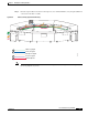
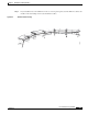
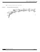
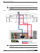
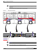
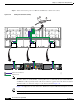
Step 12 Connect the following cables:
• Attach and route the power cables for the lighting assembly by connecting the lights to the auxiliary
control unit.
• Connect the serial cable between the projector and the auxiliary control unit.
• Connect the Ethernet cables between the codec and the auxiliary control unit.
• Connect the power cord for the auxiliary control unit to a wall outlet.
Figure 9-12 Cabling the Lighting Assembly Power Cables and Auxiliary Control Unit-to-Projector Serial Cable
Note Figure 9-12 displays the rear view of the Cisco TelePresence System 3200. Left and right are reversed.
Primary Codec
12
12
10/100 NETWORK POR TSRESETSERIAL PORTS
TelePresence
3
DE
F
6
M
N
O
9
W
XY
Z
#
2
A
B
C
5
JKL
8
T
U
V
0
OPER
1
4
G
H
I
7
P
Q
R
S
CI
SCO
IP
P
HON
E
7
9
7
0
Power
Projector
204158
RJ45 Ethernet
Auxiliary Control Unit
Auxiliary Control Unit
Auxiliary Control Unit