Installation and Upgrade Guide for Cisco Unified Videoconferencing 3515 MCU Release 5.6 August 2008 Americas Headquarters Cisco Systems, Inc. 170 West Tasman Drive San Jose, CA 95134-1706 USA http://www.cisco.
THE SPECIFICATIONS AND INFORMATION REGARDING THE PRODUCTS IN THIS MANUAL ARE SUBJECT TO CHANGE WITHOUT NOTICE. ALL STATEMENTS, INFORMATION, AND RECOMMENDATIONS IN THIS MANUAL ARE BELIEVED TO BE ACCURATE BUT ARE PRESENTED WITHOUT WARRANTY OF ANY KIND, EXPRESS OR IMPLIED. USERS MUST TAKE FULL RESPONSIBILITY FOR THEIR APPLICATION OF ANY PRODUCTS.
CONTENTS CHAPTER 1 Functionality 1-1 About the Cisco Unified Videoconferencing 3515 MCU About Cisco Unified Videoconferencing 3515 MCU Users Administrators 1-1 Moderators and Operators 1-2 Conference Users 1-2 Main Features 1-1 1-1 1-2 Port Capacities 1-4 Cisco Unified Videoconferencing 3515 MCU12 Port Capacity Cisco Unified Videoconferencing 3515 MCU24 Port Capacity About Cisco Unified Videoconferencing 3515 MCU Architecture CHAPTER 2 1-5 1-5 1-6 About Cisco Unified Videoconferencing 3515 MCU To
Contents Connecting the EMP to the LAN 2-12 About Managing and Monitoring the Cisco Unified Videoconferencing 3515 MCU Unit SNMP Management 2-13 Local Port Monitoring Connections 2-13 Performing Software Upgrades 2-13 Accessing the Cisco Unified Videoconferencing 3515 MCU Administrator Interface Registering the Online Help for the 3515 MCU CHAPTER 3 Using the Cisco Software Upgrade Utility 3-1 About the Cisco Software Upgrade Utility 3-1 Launching the Cisco Software Upgrade Utility Upgrading Softw
CH A P T E R 1 Functionality • About the Cisco Unified Videoconferencing 3515 MCU, page 1-1 • About Cisco Unified Videoconferencing 3515 MCU Users, page 1-1 • Main Features, page 1-2 • Port Capacities, page 1-4 • About Cisco Unified Videoconferencing 3515 MCU Architecture, page 1-6 • About Cisco Unified Videoconferencing 3515 MCU Topologies, page 1-7 About the Cisco Unified Videoconferencing 3515 MCU The Cisco Unified Videoconferencing 3515 MCU enables multimedia, multiparty collaboration in a
Chapter 1 Functionality Main Features Moderators and Operators Moderators and Operators can use the Conference Control interface for controlling audio, video and data connections, for selecting advanced conference view image positioning and multiple layouts, and for creating new conferences and sub-conferences. Moderators can use the Conference Control interface to view conference details and manage a specific conference.
Chapter 1 Functionality Main Features Table 1-1 Summary of Cisco Unified Videoconferencing 3515 MCU Features (continued) Feature Description Supported protocols • H.323 version 4 • SIP RFC 3261 for the Session Initiation Protocol • SCCP • H.243 for conference control • RFC 2833 for in-band DTMF with SIP • H.281 for far end camera control (FECC) • H.235 for IP-based media encryption • H.239 for standard simultaneous transmission of live video and presentation sharing feeds.
Chapter 1 Functionality Port Capacities Table 1-1 Summary of Cisco Unified Videoconferencing 3515 MCU Features (continued) Feature Description T.120 Data Collaboration support Data collaboration is defined by the T.120 standard. Data collaboration using T.120 over the video conference connection enhances the conference by providing the tools for conference participants to share data instantaneously.
Chapter 1 Functionality Port Capacities The Cisco Unified Videoconferencing 3515 MCU supports switched High Definition (HD) video service types. The switched HD service enables Voice Activated single-screen displays at up to 4 Mbps, and offers resolutions of 1280 x 720 pixels (720p) and 1920 x 1080 pixels (1080p). Switched HD service types also enable you to set a minimum downspeeding bandwidth rate that is common to all endpoints participating in a conference.
Chapter 1 Functionality About Cisco Unified Videoconferencing 3515 MCU Architecture – Unlimited number of conferences of which one can be high definition conferences at any given time. Note When using a High Definition Switched Video service type, only a single screen layout is available. High definition participants must have H.264 only and receive 720p in order to view the conference in high definition, otherwise the endpoint is considered as a standard definition endpoint.
Chapter 1 Functionality About Cisco Unified Videoconferencing 3515 MCU Topologies About Cisco Unified Videoconferencing 3515 MCU Topologies The Cisco Unified Videoconferencing 3515 MCU can work in a centralized or cascaded topology. This section describes these two options. Centralized Topology In a centralized topology, the Cisco Unified Videoconferencing 3515 MCU performs media processing for all connected terminals.
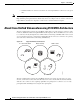
Chapter 1 Functionality About Cisco Unified Videoconferencing 3515 MCU Topologies The cascaded conference in Figure 1-3 minimizes the use of network bandwidth while distributing processing among the participating the Cisco Unified Videoconferencing 3515 MCU units. Figure 1-3 Cascaded Conference Headquarters MCU Site 2 MCU 200845 Site 1 MCU Installation and Upgrade Guide for Cisco Unified Videoconferencing 3515 MCU Release 5.
CH A P T E R 2 Setting Up Your Cisco Unified Videoconferencing 3515 MCU • Physical Description, page 2-1 • Verifying the Package Contents, page 2-2 • Mounting the Cisco Unified Videoconferencing 3515 MCU Unit in a 19-inch Rack, page 2-3 • How to Perform the Cisco Unified Videoconferencing 3515 MCU Unit Initial Configuration, page 2-4 • How to Perform the Video Processing Module Initial Configuration, page 2-8 • About Managing and Monitoring the Cisco Unified Videoconferencing 3515 MCU Unit, pag
Chapter 2 Setting Up Your Cisco Unified Videoconferencing 3515 MCU Verifying the Package Contents Cisco Unified Videoconferencing 3515 MCU Front Panel GK Reg CPU Hight SERIAL RST 10/100 Base T ALARM ACT MC SERIAL CPU Hight 157265 Figure 2-1 PWR RST 10/100 Base T Table 2-1 ALARM ACT Front Panel Components Component Description 10/100 BaseT connector An RJ-45 connector that provides the primary Ethernet connection for the IP network port.
Chapter 2 Setting Up Your Cisco Unified Videoconferencing 3515 MCU Mounting the Cisco Unified Videoconferencing 3515 MCU Unit in a 19-inch Rack Table 2-2 Package Contents with Cisco Unified Videoconferencing 3515 MCU12 or Cisco Unified Videoconferencing 3515 MCU24 Unit Product Contents Cisco Unified Videoconferencing 3515 MCU unit • Cisco Unified Videoconferencing 3515 MCU12 or Cisco Unified Videoconferencing 3515 MCU24 unit • Power cable (depending on customer location) • Terminal cable • 2 L
Chapter 2 How to Perform the Cisco Unified Videoconferencing 3515 MCU Unit Initial Configuration Fitting a Bracket for Rack Mounting 157263 Figure 2-2 Setting Up Your Cisco Unified Videoconferencing 3515 MCU Step 4 Pass the screws through the brackets and tighten them into the screw holes on each side of the Cisco Unified Videoconferencing 3515 MCU unit using a suitable screwdriver. Step 5 Insert the Cisco Unified Videoconferencing 3515 MCU unit into the 19-inch rack.
Chapter 2 Setting Up Your Cisco Unified Videoconferencing 3515 MCU How to Perform the Cisco Unified Videoconferencing 3515 MCU Unit Initial Configuration Note You can perform serial port configuration of the Cisco Unified Videoconferencing 3515 MCU unit only at startup, during a short period indicated by a 6-second countdown. Once the initialization phase is complete, the only way you can access the configuration menu is by restarting the Cisco Unified Videoconferencing 3515 MCU unit.
Chapter 2 How to Perform the Cisco Unified Videoconferencing 3515 MCU Unit Initial Configuration Setting Up Your Cisco Unified Videoconferencing 3515 MCU Procedure Step 1 Connect the RS-232 terminal cable to the PC terminal. Step 2 Connect the power cable. Step 3 Start the terminal emulation application on the PC.
Chapter 2 Setting Up Your Cisco Unified Videoconferencing 3515 MCU How to Perform the Cisco Unified Videoconferencing 3515 MCU Unit Initial Configuration Step 11 Caution At the network configuration Main menu, enter Q to save your changes and allow the device to complete the boot process. Configuration of any of the parameters other than N: Configure default network port values may alter the function of the device and should not be performed by an unauthorized person.
Chapter 2 Setting Up Your Cisco Unified Videoconferencing 3515 MCU How to Perform the Video Processing Module Initial Configuration • Enter the letter for the set of parameters that you want to configure. • Enter Q to save your changes and allow the device to complete the boot process.
Chapter 2 Setting Up Your Cisco Unified Videoconferencing 3515 MCU How to Perform the Video Processing Module Initial Configuration • Modify the Cisco Unified Videoconferencing 3515 MCU unit IP address. • Modify advanced configuration settings such as the web server port and LAN port, and to restore the factory configuration.
Chapter 2 Setting Up Your Cisco Unified Videoconferencing 3515 MCU How to Perform the Video Processing Module Initial Configuration Caution Configuration of any of the parameters other than N: Configure default network port values may alter the function of the device and should not be performed by an unauthorized person. Changing the Configuration Software Password You can use the serial port to change the configuration software password.
Chapter 2 Setting Up Your Cisco Unified Videoconferencing 3515 MCU How to Perform the Video Processing Module Initial Configuration Pointing the EMP to the Controlling Cisco Unified Videoconferencing 3515 MCU You can use the serial port to point the EMP to the IP address of the controlling Cisco Unified Videoconferencing 3515 MCU unit. Procedure Step 1 At the prompt, enter M to change the Cisco Unified Videoconferencing 3515 MCU IP address and press Enter.
Chapter 2 Setting Up Your Cisco Unified Videoconferencing 3515 MCU How to Perform the Video Processing Module Initial Configuration The network interface card settings screen appears as follows: Choose : 1 : 2 : 3 : 4 : 5 other : Step 6 - 10Mbps 100Mbps 10Mbps 100Mbps Auto Quit Half Half Full Full Duplex Duplex Duplex Duplex Enter a number between 0 and 5, inclusive, representing the required option. We recommend using 5 (Auto) and the ethernet switch port to autonegotiate speed/duplex.
Chapter 2 Setting Up Your Cisco Unified Videoconferencing 3515 MCU About Managing and Monitoring the Cisco Unified Videoconferencing 3515 MCU Unit About Managing and Monitoring the Cisco Unified Videoconferencing 3515 MCU Unit You can manage and monitor the Cisco Unified Videoconferencing 3515 MCU unit locally or from remote connections. You can also upgrade Cisco Unified Videoconferencing 3515 MCU software. SNMP Management The Cisco Unified Videoconferencing 3515 MCU unit is equipped with an SNMP agent.
Chapter 2 Accessing the Cisco Unified Videoconferencing 3515 MCU Administrator Interface Setting Up Your Cisco Unified Videoconferencing 3515 MCU You can use your web browser from any remote PC station to monitor and to configure the Cisco Unified Videoconferencing 3515 MCU unit. A web server is installed in the Cisco Unified Videoconferencing 3515 MCU unit to facilitate the use of the remote web-based monitoring and management.
Chapter 2 Setting Up Your Cisco Unified Videoconferencing 3515 MCU Registering the Online Help for the 3515 MCU Registering the Online Help for the 3515 MCU The online help files for the Cisco Unified Videoconferencing 3515 MCU Administrator and Conference Control interfaces are shipped on the Cisco Unified Videoconferencing Software CD-ROM.
Chapter 2 Setting Up Your Cisco Unified Videoconferencing 3515 MCU Registering the Online Help for the 3515 MCU Installation and Upgrade Guide for Cisco Unified Videoconferencing 3515 MCU Release 5.
CH A P T E R 3 Using the Cisco Software Upgrade Utility • About the Cisco Software Upgrade Utility, page 3-1 • Launching the Cisco Software Upgrade Utility, page 3-1 • Upgrading Software, page 3-2 About the Cisco Software Upgrade Utility The Cisco Software Upgrade Utility is an interactive GUI interface that enables you to upgrade Cisco software installed on Cisco devices.
Chapter 3 Using the Cisco Software Upgrade Utility Upgrading Software Upgrading Software You use the Software Upgrade Utility to upgrade Cisco software installed on Cisco devices. Procedure Step 1 In the General Information section of the Upgrade Utility dialog box, enter the IP address of the device you want to upgrade. Step 2 In the Login Information section, enter the administrator user name and password for the target device, as configured in the device network configuration settings.
CH A P T E R 4 Cable Connections and Pin-outs • RS-232 9-Pin Serial Port, page 4-1 • RJ-45 8-Pin IP Network Port, page 4-2 RS-232 9-Pin Serial Port Table 4-1 describes the Cisco Unified Videoconferencing 3515 MCU unit RS-232 9-pin D-type serial port pin-out configuration.
Chapter 4 Cable Connections and Pin-outs RJ-45 8-Pin IP Network Port RJ-45 8-Pin IP Network Port Table 4-2 describes the pin-out configuration of the RJ-45 IP network port. Table 4-2 Pin-out Configuration of the RJ-45 IP Network Port Pin Function I/O 1 TXD+ Output 2 TXD+ Output 3 RXD+ Input 4 NC 5 NC 6 RXD- 7 NC 8 NC Input Installation and Upgrade Guide for Cisco Unified Videoconferencing 3515 MCU Release 5.
CH A P T E R 5 Technical Specifications Table 5-1 Cisco Unified Videoconferencing 3515 MCU Unit Technical Specifications Unit Dimensions LED Indicators • Height: 1U (1.75 inches or 44.45 mm) • Width: 17.25 inches (438.15 mm) • Depth: 10 inches (254 mm) • Weight: 4.45 kg (9.
Chapter 5 Table 5-1 Technical Specifications Cisco Unified Videoconferencing 3515 MCU Unit Technical Specifications (continued) Failsafe • Watchdog timer built in Power Supply • Input 100-240VAC autoswitched • Output + 3.3VDC, + 5VDC, + 12VDC • Maximum power load 150W Installation and Upgrade Guide for Cisco Unified Videoconferencing 3515 MCU Release 5.
CH A P T E R 6 Safety • Electrical Safety, page 6-1 • ESD Procedures, page 6-2 • Batteries, page 6-2 Electrical Safety To avoid an electric shock or damage to the Cisco Unified Videoconferencing 3515 MCU unit, servicing should be performed by qualified service personnel only. To reduce the risk of damaging power surges, Cisco recommends installing an AC surge arrestor in the AC outlet from which the Cisco Unified Videoconferencing 3515 MCU unit is powered.
Chapter 6 Safety ESD Procedures Caution This is a class I unit. In Denmark, use this unit with an AC cord suited to Danish specifications. The cord should include an earthing conductor. Plug the unit into a wall socket outlet which is connected to the protective earth contact. Do not use socket outlets which are not connected to a protective earth contact! High Voltage Disconnect the Cisco Unified Videoconferencing 3515 MCU unit from the power line before removing the cover.
CH A P T E R 7 Compliance and Certifications • Safety Compliance, page 7-1 • EMC, page 7-1 • Telecom, page 7-2 • Environmental Compliance, page 7-3 Safety Compliance The Cisco Unified Videoconferencing 3515 MCU unit supports these safety standards: • UL 60950 • CSA C22.2 No.
Chapter 7 Compliance and Certifications Telecom Warning • EN 61000-3-3 • EN 61000-6-1 This is a class A product. In a domestic environment this product may cause radio interference in which case the user may be required to take adequate measures. FCC Part 15 Notice This equipment has been tested and found to comply with the limits for a Class A digital device, pursuant to Part 15 of the FCC rules.
Chapter 7 Compliance and Certifications Environmental Compliance • The telephone company may make changes in its facilities, equipment, operations or procedures that could affect the operation of the equipment. If this happens, the telephone company will provide advance notice in order for you to make necessary modifications to maintain uninterrupted service.
Chapter 7 Compliance and Certifications Environmental Compliance Installation and Upgrade Guide for Cisco Unified Videoconferencing 3515 MCU Release 5.
INDEX audio transcoding Numerics 1-3 communication interfaces 19-inch rack 2-3 mount unit communication settings 2-3 6-second countdown 9-pin serial-port 2-6 Conference Control interface 2-4, 2-6 Configuration menu 2-1 D ACT LED See LED indicators data collaboration Administrator interface DB-9 1-1, 2-13 Advanced Configuration menu 2-7, 2-9, 2-11 ALRM LED See LED indicators 1-2 2-4 Continuous Presence A architecture 5-1 1-3 1-4 2-2, 2-13 DTMF 1-4 duplex parameters 2-7, 2-1
Index set duplex parameters H set Ethernet speed H.235 1-3 interoperability H.239 1-3 IP address H.
Index pin-out configuration install and launch RJ-45 IP network port use utility 4-2 RS-232 9-pin D-type serial port 3-2 summary of features 4-1 3-1 1-2 ports RJ-45 IP 4-2 RS-232 9-pin serial power supply privacy T 4-1 5-2 T.
Index Installation and Upgrade Guide for Cisco Unified Videoconferencing 3515 MCU Release 5.