
Multilayer Switch User Manual

1-4
Catalyst 3550 Switch Hardware Installation Guide
OL-6155-01
Chapter 1 Product Overview
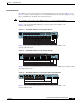
Front-Panel Description
Front-Panel Description
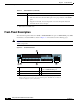
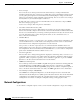
The switch front panel includes the 10/100 or 10/100/1000 Ethernet ports or 100BASE-FX ports, GBIC
module slots, and switch LEDs as shown in Figure 1-3 and described on the following pages.
Note Figure 1-3 shows the Catalyst 3550-12T switch as an example. All the Catalyst switches have
similar components.
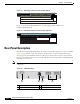
Figure 1-3 Switch Front Panel
Feature Description
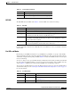
Inline Power
2
• Power for Cisco IP Phones and access points from all 10/100 Ethernet ports
• Auto-detection and control of inline power on a per-port basis on all 10/100
ports
• Support for fan-fault and overtemperature detection through the Network
Assistant and the device manager.
1. Gigabit Interface Converter
2. Only Catalyst 3550-24PWR switch
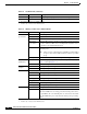
Table 1-1 Switch Features (continued)
1 Mode button 4 10/100 or 10/100/1000 Ethernet
ports or 100BASE-FX ports
1
1. Port numbering is from left to right, with port 1 on the far left. For ports grouped in pairs, the first
member of the pair (port 1) is above the second member (port 2). The GBIC slots are numbered
1 (left) and 2 (right) or 1 (above) and 2 (below).
2 Switch LEDs 5 GBIC slots
3 Port LEDs
101603
2
SPEED
SYSTEM
RPS
STAT U S
MODE
UTIL
DUPLX
1
Catalyst 3550 SERIES
1
2
345
67
8910
1 2
3
4 5