
Multilayer Switch User Manual

1-7
Catalyst 3550 Switch Hardware Installation Guide
OL-6155-01
Chapter 1 Product Overview
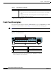
Front-Panel Description
RPS LED
The RPS LED shows the RPS status. Table 1-3 lists the LED colors and their meanings.
For more information about the Cisco RPS 300 or the Cisco RPS 675, see the documentation included
with the RPS.
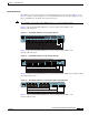
Port LEDs and Modes
Each RJ-45 port and GBIC module slot has a port LED. These port LEDs, as a group or individually,
display information about the switch and about the individual ports. The port mode determines the type
of information displayed through the port LEDs. Table 1-4 lists the mode LEDs and their associated port
modes and meanings.
To select or change a mode, press the Mode button (or Mode label on the Catalyst 3550-48 switch) until
the desired mode is highlighted. When you change port modes, the meanings of the port LED colors also
change. Table 1-5 explains how to interpret the port LED colors in different port modes.
You can also use the Mode button to activate the Express Setup program or to clear the switch IP address
and all switch settings. See the “Clearing the Switch IP Address and Configuration” section on page 3-1
for more information.
Green System is operating normally.
Amber System is receiving power but is not functioning properly.
Table 1-2 System LED (continued)
Color System Status
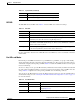
Ta b l e 1 - 3 R P S L E D
Color RPS Status
Off RPS is off or not properly connected.
Solid green RPS is connected and ready to provide back-up power, if required.
Blinking green RPS is connected but is unavailable because it is providing power to another device
(redundancy has been allocated to a neighboring device).
Solid amber The RPS is in standby mode or in a fault condition. Press the Standby/Active button
on the RPS, and the LED should turn green. If it does not, the RPS fan could have
failed. Contact Cisco Systems.
Blinking amber The internal power supply in a switch has failed, and the RPS is providing power
to the switch (redundancy has been allocated to this device).
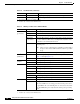
Table 1-4 Port Mode LEDs
Mode LED Port Mode Description
STATUS Port status The port status. This is the default mode.
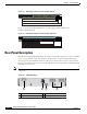
UTIL
1
Switch utilization The current bandwidth in use by the switch. (See Figure 1-4
through Figure 1-8.)
DUPLX Port duplex mode The port duplex mode: full duplex or half duplex.