
Multilayer Switch User Manual

2-8
Catalyst 3550 Switch Hardware Installation Guide
OL-6155-01
Chapter 2 Switch Installation
Installing the Switch
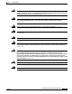
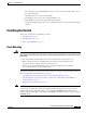
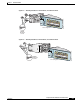
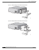
Figure 2-5 Attaching Brackets for 19-Inch Telco Racks
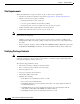
Figure 2-6 Attaching Brackets for 24-Inch Telco Racks
Attaching Brackets to the Catalyst 3550-24, 3550-24-DC, 3550-24-FX, 3550-24PWR, and
3550-48 Switches
The bracket orientation and the brackets that you use depend on whether you are attaching the brackets
for a 19-inch or a 24-inch rack. For 19-inch racks, use bracket part number 700-8209-01; for 24-inch
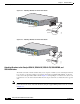
racks, use bracket part number 700-13248-01. Figure 2-7 through Figure 2-12 show how to attach each
type bracket to one side of the switch. Follow the same steps to attach the second bracket to the opposite
side.
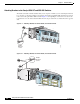
Note Before you attach the brackets on the Catalyst 3550-24-FX switch, remove the screws that are on the
bottom-front of the chassis. Attach the bracket by using the supplied Phillips flat-head screws, as shown
in Figure 2-7.
12
11
2
3
4
5
6
7
8
9
10
Catalyst 3550
SERIES
74035
Phillips
flat-head
screws
19" Configuration
12
11
2
3
4
56
7
8
9
10
Catalyst 3550
SERIES
74040
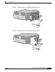
Phillips
flat-head
screws
24" Configuration