
Multilayer Switch User Manual

2-13
Catalyst 3550 Switch Hardware Installation Guide
OL-6155-01
Chapter 2 Switch Installation
Installing the Switch
Attaching the Brackets to the Switch
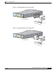
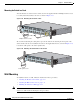
Figure 2-15 shows how to attach a 19-inch bracket to one side of the switch. Follow the same steps to
attach the second bracket to the opposite side.
Note On the Catalyst 3550-24-FX switch, remove the screws that are in the side of the chassis before you
attach the brackets.
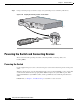
Figure 2-15 Attaching the 19-Inch Brackets for Wall Mounting
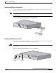
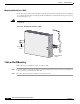
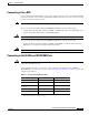
Attaching the RPS Connector Cover
If you are not using an RPS with your switch, use the two Phillips pan-head screws to attach the RPS
connector cover to the back of the switch, as shown in Figure 2-16.
Warning
If an RPS is not connected to the switch, install an RPS connector cover on the back of the switch.
Statement 265
Figure 2-16 Attaching the RPS Connector Cover on the Switch
100-240V~
5-3A
50/60Hz
CONSOLE
51368
Phillips
truss-head
screws
100-240V~
5-3A
50/60Hz
DC OUTPUT 1
CONSOLE
86483
RPS
connector
Phillips
pan-head
screws
RPS
connector
cover