
Multilayer Switch User Manual


2-15
Catalyst 3550 Switch Hardware Installation Guide
OL-6155-01
Chapter 2 Switch Installation
Installing the Optional Ground Kit
Installing the Optional Ground Kit
For switches that require a two-hole lug for grounding, you can order a kit containing the ground lug and
hardware from Cisco. For the Catalyst 3550-12G, 3550-24, and 3550-24-FX switches, order part number
NEBS-LUG-3550=.
Note When you install the ground-lug kit, you cannot connect an RPS to the switch.
To install the ground lug, you need these tools and equipment:
• Ratcheting torque screwdriver with a Phillips head that exerts up to 15 pound-force inches (lbf-in.)
or 240 ounce-force inches (ozf-in.) of pressure
• Panduit crimping tool with optional controlled-cycle mechanism (model CT-700, CT-720, CT-920,
CT-920CH, CT-930, or CT-940CH)
• 6-gauge copper ground wire (insulated or noninsulated)
• Wire-stripping tool for stripping 6-gauge wires
Note The illustrations in this section show the Catalyst 3550-12T switch as an example. Follow the same
procedure to install the ground lug on the Catalyst 3550-24 and 3550-24-FX switches.
To ground the switch to earth ground, follow these steps. Make sure to follow any grounding
requirements at your site.
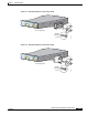
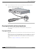
Step 1 Use the two Phillips pan-head screws to attach the RPS connector cover to the back of the switch as
shown in Figure 2-16.
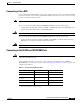
Step 2 If your ground wire is insulated, use a wire stripping tool to strip the 6-gauge ground wire to 0.5
inch (12.7 mm) ± 0.02 inch (0.5 mm). (See Figure C-1 on page C-2.)
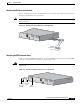
Step 3 Slide the open end of the ground lug over the exposed area of the 6-gauge wire.
Step 4 Using a Panduit crimping tool, crimp the ground lug to the 6-gauge wire. (See Figure C-2 on page C-3.)
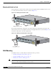
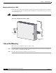
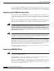
Step 5 Use the two number-10-32 screws to attach the ground lug and wire assembly to the switch rear panel
RPS connector cover, as shown in Figure 2-18.