
Multilayer Switch User Manual


2-16
Catalyst 3550 Switch Hardware Installation Guide
OL-6155-01
Chapter 2 Switch Installation
Powering the Switch and Connecting Devices
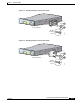
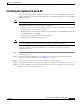
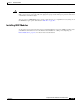
Step 6 Using a ratcheting torque screwdriver, torque each ground-lug screw to 15 lbf-in. (240 ozf-in.)
Figure 2-18 Torquing Ground-Lug Screws on the Switch
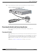
Powering the Switch and Connecting Devices
These sections describe powering the switch, connecting an RPS, connecting cables, and
inserting GBICs.
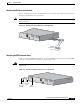
Powering the Switch
Use the supplied AC power cord to connect the AC power socket on the switch rear panel to an AC power
outlet.
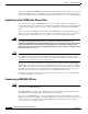
When the switch powers on, it automatically begins the power-on self-test (POST), a series of tests that
verifies that the switch functions properly. When POST completes, the system LED is green. If the
switch fails POST, the system LED is amber, and the port LED associated with the particular test is
amber.
If POST fails, see Chapter 3, “Troubleshooting,” to determine a course of action.
Torque to 15 lbf-in.
93286
100-240V~
5-3A
50/60Hz
DC OUTPUT 1
CONSOLE