
Multilayer Switch User Manual

C-2
Catalyst 3550 Multilayer Switch Hardware Installation Guide
OL-6155-01
Appendix C DC Power Connections
Connecting to DC Power
• 6-gauge copper ground wire (insulated or noninsulated)
• Four leads of 18-gauge copper wire
• Wire-stripping tools for stripping 6- and 18-gauge wires
Grounding the Switch
Warning
This equipment is intended to be grounded. Ensure that the host is connected to earth ground during
normal use.
Statement 39
Caution To make sure that the equipment is reliably connected to earth ground, follow the grounding procedure
instructions, and use a UL-listed lug suitable for number-6 AWG wire and two number-10-32 ground-lug
screws.
Warning
When installing the unit, always make the ground connection first and disconnect it last.
Statement 42
To ground the switch to earth ground, follow these steps. Make sure to follow any grounding
requirements at your site.
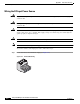
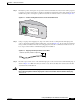
Step 1 Locate and remove the ground lug and the two number-10-32 ground-lug screws from the rear panel of
the switch. (See Figure C-3 for location.) Use a standard Phillips screwdriver or a ratcheting torque
screwdriver with a Phillips head. Set the screws and the ground lug aside.
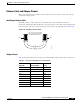
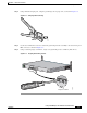
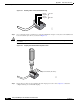
Step 2 If your ground wire is insulated, use a wire stripping tool to strip the 6-gauge ground wire to 0.5
inch (12.7 mm) ± 0.02 inch (0.5 mm), as shown in Figure C-1.
Figure C-1 Stripping the Ground Wire
Step 3
Slide the open end of the ground lug over the exposed area of the 6-gauge wire.
Insulation
Wire lead
0.5 in. (12.7 mm)
±
0.02 in. (0.5 mm)
60528