Configuring Voice over IP for the Cisco 3600 Series This chapter shows you how to configure Voice over IP (VoIP) on the Cisco 3600 series. For a description of the commands used to configure Voice over IP, refer to the “Voice-Related Commands” chapter in the Voice, Video, and Home Applications Command Reference. VoIP enables a Cisco 3600 series router to carry voice traffic (for example, telephone calls and faxes) over an IP network.
List of Terms 5 The session application then runs the H.323 session protocol to establish a transmission and a reception channel for each direction over the IP network. If the call is being handled by a PBX, the PBX forwards the call to the destination telephone. If RSVP has been configured, the RSVP reservations are put into effect to achieve the desired quality of service over the IP network.
Prerequisite Tasks PBX—Private Branch Exchange. Privately-owned central switching office. PLAR—Private Line Auto Ringdown. This type of service results in a call attempt to some particular remote endpoint when the local extension is taken off-key. POTS—Plain Old Telephone Service. Basic telephone service supplying standard single line telephones, telephone lines, and access to the public switched telephone network. POTS dial peer—Dial peer connected via a traditional telephony network.
Voice over IP Configuration Task List Voice over IP Configuration Task List To configure Voice over IP on the Cisco 3600 series, you need to complete the following tasks: 1 Configure IP Networks for Real-Time Voice Traffic Configure your IP network to support real-time voice traffic. Fine-tuning your network to adequately support VoIP involves a series of protocols and features geared toward Quality of Service (QoS).
Configure IP Networks for Real-Time Voice Traffic (b) VoIP—Dial peer describing the characteristics of a packet network connection; in the case of Voice over IP, this is an IP network. VoIP peers point to specific VoIP devices. To minimally configure a VoIP peer, you need to configure the following two characteristics: associated destination telephone number and a destination IP address. Use the destination-pattern command to define the destination telephone number associated with a VoIP peer.
Configure IP Networks for Real-Time Voice Traffic The important thing to remember is that QoS must be configured throughout your network—not just on the Cisco 3600 series devices running VoIP—to improve voice network performance. Not all QoS techniques are appropriate for all network routers. Edge routers and backbone routers in your network do not necessarily perform the same operations; the QoS tasks they perform might differ as well.
Configure Multilink PPP with Interleaving Configure Multilink PPP with Interleaving Multi-class Multilink PPP Interleaving allows large packets to be multilink-encapsulated and fragmented into smaller packets to satisfy the delay requirements of real-time voice traffic; small real-time packets, which are not multilink-encapsulated, are transmitted between fragments of the large packets.
Configure IP Networks for Real-Time Voice Traffic For more information about Multilink PPP, refer to the “Configuring Media-Independent PPP and Multilink PPP” chapter in the Dial Solutions Configuration Guide.
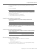
Configure RTP Header Compression You should configure RTP header compression if the following conditions exist in your network: • • Slow links Need to save bandwidth Note RTP header compression should not be used on links greater than 2 Mbps. Perform the following tasks to configure RTP header compression for Voice over IP. The first task is required; the second task is optional.
Configure Frame Relay for Voice over IP Configure Custom Queuing Some QoS features, such as IP RTP reserve and custom queuing, are based on the transport protocol and the associated port number. Real-time voice traffic is carried on UDP ports ranging from 16384 to 16624. This number is derived from the following formula: 16384 = 4(number of voice ports in the Cisco 3600 series router) Custom Queuing and other methods for identifying high priority streams should be configured for these port ranges.
Frame Relay for Voice over IP Configuration Example Note Lowering the MTU size affects data throughput speed. • CIR equal to line rate—Make sure that the data rate does not exceed the CIR. This is accomplished through generic traffic shaping. — Use IP Precedence to prioritize voice traffic. — Use compressed RTP to minimize voice packet header size. • Traffic shaping—Use adaptive traffic shaping to throttle back the output rate based on the BECN.
Configure Number Expansion • • Fair-queuing is enabled. IP RTP header compression is enabled. The subinterface has been configured as follows: • • • • • • MTU size is inherited from the main interface. IP address for the subinterface is specified. Bandwidth is set to 64 kbps. Generic traffic shaping is enabled with 32 kbps CIR where Bc=4000 bits and Be=4000 bits. Frame Relay DLCI number is specified. IP RTP header compression is enabled.
Configure Number Expansion Figure 5 Sample Voice over IP Network 729 555-1001 729 555-1002 408 115-1001 729 555-1000 408 116-1002 Voice port 0:D Cisco 3600 Router 1 WAN 10.1.1.1 729 555-1003 T1 ISDN PRI Voice port 0:D IP cloud WAN 10.1.1.2 1:D T1 ISDN PRI 15586 Cisco 3600 Router 2 408 117-1003 Table 5 shows the number expansion table for this scenario. Table 5 Sample Number Expansion Table Extension Destination Pattern Num-Exp Command Entry 5.... 40811..... num-exp 5.... 408115.... 6.
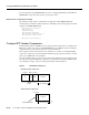
Configure Dial Peers Configure Dial Peers The key point to understanding how Voice over IP functions is to understand dial peers. Each dial peer defines the characteristics associated with a call leg, as shown in Figure 6 and Figure 7. A call leg is a discrete segment of a call connection that lies between two points in the connection. All the call legs for a particular connection have the same connection ID.
Inbound versus Outbound Dial Peers POTS peers associate a telephone number with a particular voice port so that incoming calls for that telephone number can be received and outgoing calls can be placed. VoIP peers point to specific devices (by associating destination telephone numbers with a specific IP address) so that incoming calls can be received and outgoing calls can be placed. Both POTS and VoIP peers are needed to establish Voice over IP connections.
Configure Dial Peers Figure 9 Outgoing Calls from the Perspective of POTS Dial Peer 2 Destination Source IP cloud Dial peer 1 Dial peer 2 Voice port 1/0/0 Dial peer 3 Voice port 1/0/0 10.1.1.2 10.1.2.2 (408) 555-4000 Dial peer 4 (310) 555-1000 S6614 POTS call leg VoIP call leg To complete the end-to-end call between dial peer 1 and dial peer 4 as illustrated in Figure 9, enter the following commands on router 10.1.1.2: dial-peer voice 4 pots destination-pattern 1310555....
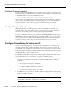
Configure POTS Peers Configure POTS Peers Once again, POTS peers enable incoming calls to be received by a particular telephony device. To configure a POTS peer, you need to uniquely identify the peer (by assigning it a unique tag number), define its telephone number(s), and associate it with a voice port through which calls will be established. Under most circumstances, the default values for the remaining dial-peer configuration commands will be sufficient to establish connections.
Configure Dial Peers PBX Incoming and Outgoing POTS Call Legs Cisco 3600 Incoming call leg IP cloud Cisco 3600 PBX Outgoing call leg 15564 Figure 10 Unless otherwise configured, when a call arrives on the access server, the server presents a dial tone to the caller and collects digits until it can identify the destination dial peer. After the dial peer has been identified, the call is forwarded through the next call leg to the destination.
Configure VoIP Peers To configure DID for a particular POTS dial peer, use the following commands beginning in global configuration mode: Step Command Purpose 1 dial-peer voice number pots Enter the dial-peer configuration mode to configure a POTS peer. 2 direct-inward-dial Specify direct inward dial for this POTS peer. Note Direct inward dial is configured for the calling POTS dial peer.
Optimize Dial Peer and Network Interface Configurations Validation Tips You can check the validity of your dial-peer configuration by performing the following tasks: • If you have relatively few dial peers configured, you can use the show dial-peer voice command to verify that the data configured is correct. Use this command to display a specific dial peer or to display all configured dial peers.
Configure RSVP for Dial Peers To give real-time voice traffic precedence over other IP network traffic, use the following commands, beginning in global configuration mode: Step Command Purpose 1 dial-peer voice number voip Enter the dial-peer configuration mode to configure a VoIP peer. 2 ip precedence number Select a precedence level for the voice traffic associated with that dial peer.
Optimize Dial Peer and Network Interface Configurations To generate an SNMP trap message if the reserved QoS is less than the configured value for a selected VoIP peer, use the following commands, beginning in global configuration mode: Step Command Purpose 1 dial-peer voice number voip Enter the dial-peer configuration mode to configure a VoIP peer. 2 acc-qos [best-effort | controlled-load | guaranteed-delay] Specify the QoS value below which an SNMP trap will be generated.
Configure Voice over IP using a Trunk Connection Configure VAD for a VoIP Dial Peer To disable the transmission of silence packets for a selected VoIP peer, use the following commands beginning in global configuration mode: Step Command Purpose 1 dial-peer voice number voip Enter the dial-peer configuration mode to configure a VoIP peer. 2 vad Disable the transmission of silence packets (enabling VAD).
Configure Voice over IP using a Trunk Connection The routers on both sides of the Voice over IP connection must be configured for trunk connections. For the scenario described in Figure 11, configure Router A to support trunk connections as follows: configure terminal voice-port 1/0/0 connection trunk +15105554000 dial-peer voice 10 pots destination-pattern +13085551000 port 1/0/0 dial-peer voice 100 voip session-target ipv4:172.20.10.
Configure Voice over IP for Microsoft NetMeeting Configure a Trunk Connection To configure virtual trunk connections in a VoIP network, use the following commands beginning in global configuration mode: Step Command Purpose 1 dial-peer voice number pots Enter dial-peer configuration mode and define a tag number for a POTS dial peer. 2 destination-pattern [+]string Specify the telephone number associated with the POTS dial peer.
Voice over IP Configuration Examples Configure Microsoft NetMeeting for Voice over IP To configure NetMeeting to work with Voice over IP, complete the following steps: Step 1 From the Tools menu in the NetMeeting application, select Options. NetMeeting will display the Options dialog box. Step 2 Click the Audio tab. Step 3 Click the “Calling a telephone using NetMeeting” check box. Step 4 Enter the IP address of the Cisco AS5300 in the IP address field. Step 5 Under General, click Advanced.
FXS-to-FXS Connection Using RSVP R12-e establish the WAN connection between the two offices. Because one POTS telephony device is connected to Router RLB-2, it has also been configured for only one POTS peer and one VoIP peer. Note In this example, only the calling end (Router RLB-1) is request RSVP. Figure 12 illustrates the topology of this FXS-to-FXS connection example.
Voice over IP Configuration Examples clockrate 64000 router igrp 888 network 10.0.0.0 network 20.0.0.0 network 40.0.0.
FXS-to-FXS Connection Using RSVP Configuration for Router RLB-w hostname rlb-w ! Configure serial interface 1/0 interface Serial1/0 ip address 10.0.0.2 255.0.0.0 ! Configure RTP header compression ip rtp header-compression ip rtp compression-connections 25 ! Enable RSVP on this interface ip rsvp bandwidth 96 96 fair-queue 64 256 3 ! Configure serial interface 1/3 interface Serial1/3 ip address 20.0.0.1 255.0.0.
Voice over IP Configuration Examples ! Configure IGRP router igrp 888 network 10.0.0.0 network 20.0.0.0 network 40.0.0.0 Configuration for Router RLB-2 hostname r1b-2 ! Create pots dial peer 2 dial-peer voice 2 pots ! Define its associated telephone number and voice port destination-pattern +4155554000 port 1/0/0 ! Create voip dial peer 20 dial-peer voice 20 voip !Define its associated telephone number and IP address destination-pattern +4085554000 session target ipv4:10.0.0.
Linking PBX Users with E&M Trunk Lines Linking PBX Users with E&M Trunk Lines The following example shows how to configure Voice over IP to link PBX users with E&M trunk lines. In this example, a company wants to connect two offices: one in San Jose, California and the other in Salt Lake City, Utah. Each office has an internal telephone network using PBX, connected to the voice network by an E&M interface.
Voice over IP Configuration Examples voice-port 1/0/1 signal immediate operation 4-wire type 2 !Configure the serial interface interface serial 0/0 description serial interface type dce (provides clock) clock rate 2000000 ip address 172.16.1.123 no shutdown Configuration for Router SLC hostname saltlake !Configure pots dial peer 1 dial-peer voice 1 pots destination-pattern 119.... port 1/0/0 !Configure pots dial peer 2 dial-peer voice 2 pots destination-pattern 119....
PSTN Gateway Access Using FXO Connection PSTN Gateway Access Using FXO Connection The following example shows how to configure Voice over IP to link users with the PSTN gateway using an FXO connection. In this example, users connected to Router SJ in San Jose, California can reach PSTN users in Salt Lake City, Utah via Router SLC. Router SLC in Salt Lake City is connected directly to the PSTN through an FXO interface. Figure 14 illustrates the topology of this connection example.
Voice over IP Configuration Examples Configuration for Router SLC ! Configure pots dial peer 1 dial-peer voice 1 pots destination-pattern 9........... port 1/0/0 ! Configure voip dial peer 2 dial-peer voice 2 voip destination-pattern +14085554000 session target ipv4:172.16.1.123 ! Configure serial interface interface serial 0/0 ip address 172.16.65.
PSTN Gateway Access Using FXO Connection (PLAR Mode) Configuration for Router SJ ! Configure pots dial peer 1 dial-peer voice 1 pots destination-pattern +14085554000 port 1/0/0 ! Configure voip dial peer 2 dial-peer voice 2 voip destination-pattern 9........... session target ipv4:172.16.65.182 ! Configure the serial interface interface serial 0/0 clock rate 2000000 ip address 172.16.1.123 no shutdown Configuration for Router SLC ! Configure pots dial peer 1 dial-peer voice 1 pots destination-pattern 9...
Voice over IP Configuration Examples VC-48 Voice, Video, and Home Applications Configuration Guide