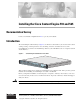
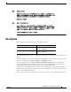
Installing the Cisco Content Engine 510 and 565 Documentation Survey Is Cisco documentation helpful? Click here to give us your feedback. Introduction The Content Engine 510 and 565 (see Figure 1) are Internet content delivery devices that offer content caching, hosting, content replication, video streaming, and other content-based services. The Content Engine is positioned on the WAN edge between your small business site or enterprise network and the Internet.
Contents Contents This document contains the following sections: • If You Need More Information, page 2 • Warning Definition, page 3 • Description, page 7 • Installation Prerequisites, page 9 • Safety Guidelines, page 10 • Operating Specifications, page 12 • Installing a Content Engine 510 or 565 Unit, page 14 • Connecting Cables, page 19 • Connecting Power and Booting the System, page 19 • Checking the LEDs, page 20 • Accessing the ACNS Software on the Content Engine, page 22 • Remo
Warning Definition – Cisco ACNS Software Caching and Streaming Configuration Guide, Release 5.1 – Cisco ACNS Software Command Reference, Release 5.1 • For information about configuring the Websense software, go to the following web site: http://www.websense.com • For information about configuring the SmartFilter software, go to the following web site: http://www.securecomputing.com Warning Definition Warning IMPORTANT SAFETY INSTRUCTIONS This warning symbol means danger.
Warning Definition Attention IMPORTANTES INFORMATIONS DE SÉCURITÉ Ce symbole d'avertissement indique un danger. Vous vous trouvez dans une situation pouvant entraîner des blessures ou des dommages corporels. Avant de travailler sur un équipement, soyez conscient des dangers liés aux circuits électriques et familiarisez-vous avec les procédures couramment utilisées pour éviter les accidents.
Warning Definition ¡Advertencia! INSTRUCCIONES IMPORTANTES DE SEGURIDAD Este símbolo de aviso indica peligro. Existe riesgo para su integridad física. Antes de manipular cualquier equipo, considere los riesgos de la corriente eléctrica y familiarícese con los procedimientos estándar de prevención de accidentes. Al final de cada advertencia encontrará el número que le ayudará a encontrar el texto traducido en el apartado de traducciones que acompaña a este dispositivo.
Warning Definition Installing the Cisco Content Engine 510 and 565 6 78-14731-02
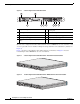
Description Description This document describes the following Content Engine models: Model Product Number Content Engine 510 CE-510A-80GB-K9 CE-510A-160GB-K9 Content Engine 565 CE-565A-72GB-K9 CE-565A-144GB-K9 The Content Engine 510 and 565 are configured for AC-input power and have a single AC-input power supply. Your Content Engine comes with an integrated dual-port Ethernet controller. This controller provides an interface for connecting to 10-Mbps, 100-Mbps, or 1000-Mbps networks.
Description Figure 2 Content Engine 510 and 565 Back Panel 2 83108 1 9 8 7 6 5 4 3 1 AC power receptacle 2 PCI slot 1; Fibre Channel or MPEG A/V decoder ports 3 Serial port 4 Ethernet 2 receptacle 5 Ethernet 1 receptacle 6 Onboard video port (not supported) 7 Mouse port (not supported) 8 Keyboard port (not supported) 9 PCI slot 2; SCSI adapter and port (CE-565 only) Models can be configured with either a Fibre Channel card or an MPEG A/V decoder card.
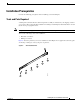
Installation Prerequisites Installation Prerequisites Consider the following prerequisites before installing your Content Engine. Tools and Parts Required A sliding rail rack-mount kit and cable management assembly are included in your shipping container accessory box. The rack-mount kit is suitable for mounting Content Engine 510 and 565 units in 19-inch (48.26-cm) 4-post equipment racks. Note A 2-post rack-mounting option contains angle brackets for attaching the chassis to a 2-post rack.
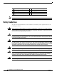
Safety Guidelines Note 1 Slide rail assemblies (2) 2 M3.5 screws with lock washers (3) 3 M4 screws (6) 4 M6 screws (10) 5 Clip nuts (10) 6 Cage nuts (10) 7 Cage nut insertion tool (1) The right and left slide rails are identical. Safety Guidelines To reduce the risk of bodily injury, electrical shock, fire, and damage to the equipment, observe the following precautions.
Safety Guidelines General Precautions Observe the following general precautions for using and working with your system: • Observe and follow service markings. Do not service any Cisco product except as explained in your system documentation. Opening or removing covers that are marked with the triangular symbol with a lightning bolt may expose you to electrical shock. Components inside these compartments should be serviced only by an authorized service technician.
Operating Specifications Protecting Against Electrostatic Discharge Static electricity can harm delicate components inside your system. To prevent static damage, discharge static electricity from your body before you touch any of your system’s electronic components. You can do so by touching an unpainted metal surface on the chassis.
Operating Specifications Table 1 Content Engine 510 and 565 Operating Specifications (continued) Specification Description Electrical input • Sine-wave input (47–63 Hz) required • Input voltage low range: – Minimum: 100 VAC – Maximum: 127 VAC • Input voltage high range: – Minimum: 200 VAC – Maximum: 240 VAC • Input kilovolt-amperes (kVA), approximately: – Minimum: 0.087 kVA – Maximum: 0.
Installing a Content Engine 510 or 565 Unit Installing a Content Engine 510 or 565 Unit Place the unit in the desired location. You can mount it in a rack for your convenience, or place it on a solid, stable surface. If you do not plan to install the Content Engine in an equipment rack, proceed to the “Installing the Chassis on a Tabletop” section on page 18. Racks are marked in vertical increments of 1.75 inches (4.44 cm). Each increment is referred to as a rack unit (RU). A 1-RU device is 1.75 inches (4.
Installing a Content Engine 510 or 565 Unit Step 2 Remove the inner slide rails (labeled 3 in Figure 7) from the slide rail assemblies by pressing the release latches (labeled 2 in Figure 7) on the sides of the slide rail assemblies.
Installing a Content Engine 510 or 565 Unit Step 3 Place an inner slide rail at the alignment marker (labeled 1 in Figure 8) as indicated by the arrow on the side of the Content Engine. Use two M4 screws to secure the inner slide rail to the Content Engine. Repeat this step to attach the other inner slide rail to the Content Engine.
Installing a Content Engine 510 or 565 Unit Step 4 Insert the tab (labeled 1 in Figure 9) on the rear of the slide rail assembly through the center hole between the two clip nuts or cage nuts on the rear flange. Figure 9 Attaching the Slide Rails to the Rack Front Rear 1 2 83199 3 Step 5 1 Tab 3 Rear flange 2 Adjustment screw Align the slide rail assembly to the front flange on the rack and insert and tighten two M6 screws to secure the slide rail to the front flange. (See Figure 9.
Installing a Content Engine 510 or 565 Unit Step 8 Tighten the captive screw (labeled 1 in Figure 10) on each side of the front of the Content Engine to secure the Content Engine to the rack. Inserting the Inner Slide Rails 83201 Figure 10 1 Step 9 Attach the power cords and the Ethernet cables to the Content Engine. (See the “Connecting Cables” section on page 19.
Connecting Cables Follow these steps to install the Content Engine on a workbench or tabletop: Step 1 Remove any debris and dust from the tabletop or workbench, as well as from the surrounding area. Also make sure that your path between the Content Engine and its new location is unobstructed. Step 2 Attach the rubber feet to the bottom of the chassis. The rubber feet have an adhesive backing. Peel the protective tape off the adhesive and stick the feet to the bottom of a clean chassis surface.
Checking the LEDs Step 3 Connect the other end of the power cord to a power source at your installation site. Step 4 Power up all externally connected devices. Step 5 Press the power control button on the front of the Content Engine. The system should begin booting. Once the operating system boots, you are ready to initialize the basic software configuration. (Refer to the software configuration guide or user guide that shipped with your system.
Checking the LEDs Figure 12 Back Panel LEDs 2 83110 1 6 Table 3 5 4 3 Back Panel LEDs Indicator Color State Description 1 Green On Indicates that the speed of the Ethernet LAN is 1000BASE-TX. Off Indicates that the speed of the Ethernet LAN is 10/100BASE-TX. Ethernet 1 link 2 Ethernet 1 activity Green Blinking Indicates that Ethernet port 1 has an active connection to the LAN.
Accessing the ACNS Software on the Content Engine Table 4 Fibre Channel Card LEDs LED State Meaning Green On Power is on. Amber On Green On Amber Off Green Off Amber On Green Off Amber Flashing Green Flashing Amber Flashing Fibre Channel is on line. Signal acquired (the Fibre Channel card firmware is performing or waiting to perform Fibre Channel loop initialization). Loss of synchronization. Firmware error.
Removing or Replacing a Content Engine To connect the Content Engine to a terminal or PC, follow these steps: Step 1 Connect the blue console cable to the blue console port on the back of the Content Engine. Step 2 Connect the DB-9 end of the console cable to the console port (also called the serial port) on your PC. If this adapter does not fit your PC console port, you must provide an adapter that fits.
Cisco One-Year Limited Hardware Warranty Terms Cisco One-Year Limited Hardware Warranty Terms There are special terms applicable to your hardware warranty and various services that you can use during the warranty period. Your formal Warranty Statement, including the warranty applicable to Cisco software, is included on the CD that accompanies your Cisco product. Follow these steps to access and download the Cisco Information Packet and your warranty document from the CD or from Cisco.com. 1.
Obtaining Documentation To Receive a Return Materials Authorization (RMA) Number Contact the company from whom you purchased the product. If you purchased the product directly from Cisco, contact your Cisco Sales and Service Representative. Complete the information below, and keep it for reference.
Obtaining Technical Assistance Ordering Documentation You can find instructions for ordering documentation at this URL: http://www.cisco.com/univercd/cc/td/doc/es_inpck/pdi.htm You can order Cisco documentation in these ways: • Registered Cisco.com users (Cisco direct customers) can order Cisco product documentation from the Networking Products MarketPlace: http://www.cisco.com/en/US/partner/ordering/index.shtml • Nonregistered Cisco.
Obtaining Additional Publications and Information Opening a TAC Case The online TAC Case Open Tool (http://www.cisco.com/tac/caseopen) is the fastest way to open P3 and P4 cases. (Your network is minimally impaired or you require product information). After you describe your situation, the TAC Case Open Tool automatically recommends resources for an immediate solution. If your issue is not resolved using these recommendations, your case will be assigned to a Cisco TAC engineer.
Obtaining Additional Publications and Information • Packet magazine is the Cisco quarterly publication that provides the latest networking trends, technology breakthroughs, and Cisco products and solutions to help industry professionals get the most from their networking investment. Included are networking deployment and troubleshooting tips, configuration examples, customer case studies, tutorials and training, certification information, and links to numerous in-depth online resources.