Trademarks Meraki, Meraki MR62, MR66, amd Meraki Cloud Controller are trademarks of Meraki, Inc. Other brand and product names are registered trademarks or trademarks of their respective holders. Warranty Meraki, Inc. provides a one year warranty on this product. Warranty details may be found at www.meraki.com/support.
Table of Contents 1 Scope of Document and Related Publications 4 2 MR66 Overview 2.1 Package Contents 2.2 Understanding the MR66 2.3 Antennas and Ports 2.4 Power Source Options 2.5 Factory Reset Button 2.6 LED Indicators and Run Dark Mode 5 5 6 8 9 9 9 3 Pre-Install Preparation 10 3.1 Configure Your Network in Dashboard 3.2 Check and Upgrade Firmware 3.3 Check and Configure Firewall Settings 3.4 Assigning IP Addresses to MR66s 3.4.1 Dynamic Assignment 3.4.2 Static Assignment 3.5 Collect Tools 3.
1 Scope of Document and Related Publications The MR62/66 Hardware Installation Guide describes the installation procedure for the MR62 and MR66 access points. Note: All instructions in this hardware installation guide reference the MR66 but apply equally to the MR62, except where noted. Additional reference documents are available online at meraki.com/support/#documentation.
2 MR66 Overview The Meraki MR66 is an enterprise-class, 802.11n access point designed for rugged environments. When connected to the Meraki Cloud Controller, the MR66 enables the creation of high-speed and reliable net works that cover large outdoor and industrial areas quickly, easily, and cost-effectively. 2.
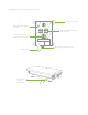
2.2 Understanding the MR66 Your Meraki MR66 has the following features: Accessory antenna attachment holes Mount attachment posts (4x) LED indicators Grounding post 5 GHz 5 GHz Factory reset button Mount Vent Vent The vent allows pressure and humidity equalization between the interior and the enviroment. This prevents internal condensation and maintains a water proof seal. Grounding Post Provides an attachment point on the access point for the grounding strap (included).
Your MR66 mount plate has the following features: Mounting holes (4x) Mount plate attachment slots (4x) Vertical orientation mounting strap slots (2x) Horizontal orientation mounting strap slots (2x) Mount plate attachment screw Release tab Mount plate ground attachment 7
2.3 Antennas and Ports The Meraki MR66 has two 802.11n radios (the MR62 has one radio). Each radio has two external antenna connectors; both connectors for a particular radio should be attached to the same type of antenna. The 5 GHz radio is used for mesh or client communication. The 2.4 GHz radio is primarily used for client communication. However, it can also communicate with Meraki 2.4 GHz access points. Meraki offers a number of different antennas for use with the MR66.
2.4 Power Source Options The MR66 access point can be powered using either a third-party 802.3af PoE switch or the Meraki 802.3af PoE injector (sold separately). 2.5 Factory Reset Button The Factory Reset Button restores the MR66 to its original factory settings by deleting all configuration information stored on the unit. 2.6 LED Indicators and Run Dark Mode Your MR66 is equipped with a series of LED lights on the front of the unit to convey information about system functionality and performance.
3 Pre-Install Preparation You should complete the following steps before going on-site to perform an installation. 3.1 Configure Your Network in Dashboard Meraki recommends that you add your MR66 to a network in Dashboard before mounting it in the field. The following is a brief overview only of the steps required to add an MR66 to your network. For detailed instructions about creating, configuring and managing Meraki wireless networks, refer to the Meraki Cloud Controller Manual (meraki.
3.4 Assigning IP Addresses to MR66s All gateway MR66s (MR66s with Ethernet connections to the LAN) must be assigned routable IP addresses. These IP addresses can be dynamically assigned via DHCP or statically assigned. 3.4.1 Dynamic Assignment When using DHCP, the DHCP server should be configured to assign a static IP address for each MAC address belonging to a Meraki AP. Other features of the wireless network, such as 802.1X authentication, may rely on the property that the APs have static IP addresses.
3.5 Collect Tools You will need the following tools to perform an installation: Required Flat-head screwdriver Recommended Phillips screwdriver Drill with appropriate bits for mounting wall anchors (if mounting to a wall) Tin snips (if mounting with hose clamps) Power screwdriver with 5/16” (8 mm) nut driver, Phillips & flat heads 3.6 Collect Additional Hardware for Installation Required Network cables with RJ45 connectors long enough for your particular mounting location 802.
4 Installation Instructions 4.1 Choose Your Mounting Location A good mounting location is important to getting the best performance out of your MR66 access point. Keep the following in mind: 1. The device should have unobstructed line of sight to most coverage areas. For example, if installing in an office filled with workspaces divided by mid-height cubicle walls, installing on the ceiling or high on a wall would be ideal. 2. Power over Ethernet supports a maximum cable length of 300 ft (100 m). 3.
4.2.1 Remove the Mount Plate from the Access Point Before installing the mount plate, you must remove it from the back of the access point. 1. Unscrew the mount plate attachment screw. 2. Lift the mount plate release tab upwards. . 3. While holding the mount plate release tab up, slide the mount plate off the access point in the direction shown below.
4.2.2 Attach the Mount Plate The MR66 mount plate can be used to install your access point in a wide range of scenarios. 4.2.2.1 Wall or Solid Ceiling Mount Using Mount Plate Using included wall anchors and screws, attach the mount plate to your mounting wall or ceiling. It is recommended that the MR66 be mounted to a wall or solid ceiling using the mount plate for physical security reasons. 4.2.2.2 Pole Mount Using Mount Plate Use the included mounting straps to mount the AP to a pole less than 3.
4.2.3 Mount the MR66 Insert the posts on the back of the access point into the attachment slots on the mount plate.
4.2.3.1 Attach Antennas Remove protective plastic covers from all four N-type RF connectors. Attach appropriate antennas (and protective boots if included). 4.2.3.2 Aim Antennas If you are using directional antennas, aim them appropriately to ensure optimal performance for your specific network topography. Omnidirectional antennas perform best in a mesh network when oriented vertically.
4.2.3.3 Powering the MR66 with the Meraki 802.3af Power over Ethernet Injector (sold separately) 1. Plug the power cord into the PoE Injector and the other end into wall power. 2. Plug an Ethernet cable that is connected to an active Ethernet connection into the “IN“ port on the injector. 3. Route Ethernet cable from the “OUT“ port on the injector to the Ethernet port in the bay of the MR66. For more details, see Meraki 802.3af Power Over Ethernet Injector datasheet. PoE 3 LAN PoE 2 AC 1 LAN 4.2.3.
4.2.3.5 Attach Power over Ethernet to the MR66 1. Remove the dust cover from the Ethernet port of the MR66. Unscrew it with a coin or flathead screwdriver. 2. Route the Ethernet cable from the PoE Injector “OUT” port to the MR66. 3. Install a Cable Gland on the MR66 end of the cable.
4. Plug the Ethernet cable into the Ethernet port of the Meraki MR66. a. Connect the cable to the Ethernet port on the MR66. b. Screw the gland body into the threaded hole of the port. Use an adjustable wrench to make sure the gland body is fully seated in the hole. c. Insert the split ring gasket into the gland body. d. Screw the cap tightly onto the gland. You may need a wrench to fully tighten the cap, but take care not to damage the cable in the process. Optional: Make the MR66 a gateway 1.
4.4 Verify Device Functionality and Test Network Coverage 1. Check LEDs The Radio Power LED should be solid green. If it is flashing orange, the firmware is automatically upgrading and the LED should turn green when the upgrade is completed (normally in under thirty minutes). If the device is a gateway, the Ethernet LED and the four Signal Strength LEDs should be green as well.