Quick Start Guide Cisco 600W Redundant Power System Quick Start Guide with License and Warranty Information 1 Cisco 90-Day Limited Hardware Warranty Terms 2 Documents, Equipment, and Tools 3 Install the Chassis 4 Connect Cables 5 Power Up the Equipment 6 Obtaining Documentation 7 Obtaining Technical Assistance 8 Obtaining Additional Publications and Information
1 Cisco 90-Day Limited Hardware Warranty Terms There are special terms applicable to your hardware warranty and various services that you can use during the warranty period. Your formal Warranty Statement, including the warranty applicable to Cisco software, is included on the CD that accompanies your Cisco product. Follow these steps to access and download the Cisco Information Packet and your warranty document from the CD or from Cisco.com. 1. Launch your browser, and go to this URL: http://www.cisco.
To Receive a Return Materials Authorization (RMA) Number Contact the company from whom you purchased the product. If you purchased the product directly from Cisco, contact your Cisco Sales and Service Representative.
Related Hardware Installation Additional hardware installation documents provide information about installing interconnection adapters in routers and about rack-mounting the Cisco RPS. You can access these document sat Cisco Product Documentation > Access Servers and Access Routers > Cisco 600W Redundant Power System > Procedures for Spare Parts: Adapter Plates and Rack Brackets.
3 Install the Chassis Safety Information For safety information you need to know before working on your Cisco RPS, see the Regulatory Compliance and Safety Information document that accompanied this device. Chassis Installation Methods Warning Only trained and qualified personnel should be allowed to install or replace this equipment. To see translations of the warnings that appear in this publication, refer to the Regulatory Compliance and Safety Information document that accompanied this device.
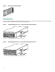
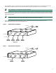
Brackets for Telco Rack-Mounting 10254 Figure 2 Attaching Brackets Attach the mounting brackets to the chassis as shown in Figure 3, Figure 4, or Figure 5, using the screws provided in the bracket kit. Use a number 2 Phillips screwdriver to install the bracket screws. Bracket Attachment for 19-, 23-, or 24-Inch Rack with Front Panel Forward H9696 Figure 3 DC STATUS 1 2 3 4 FAN TEMP Note: The second bracket attaches to the other side of the chassis.
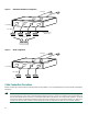
Bracket Attachment for Telco Rack with Rear Panel Forward 11540 Figure 5 DC OUTPUT 3 DC OUTPUT 4 Note: The second bracket attaches to the other side of the chassis. The brackets can also be installed with the Cisco RPS front panel forward. Installing the Chassis in a Rack Install the chassis in the rack. Rack-mounting screws are not provided with the router. Use two screws for each side (supplied with the rack).
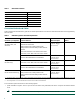
Table 1 RPS Interface Modules Powered Device RPS Interface Module Cisco 2500 series, Cisco MC3810 ACS-2500RPS= Cisco 2600 series ACS-2600RPS= Cisco 3620 ACS-3620RPS= Cisco 3640 ACS-3640RPS= Cisco 3725 ACS-3725RPS= Cisco 4000 series ACS-4000RPS= Connection Methods and Cables Table 2 summarizes the redundancy options and cable requirements for the various external devices that can be supported by the Cisco RPS.
• Fully redundant—Figure 7. The power source is fully redundant because there are two AC input modules and two DC output power modules connected to each external device. If any power module fails, there is a full backup. Note This configuration is not supported for switches and hubs. • Redundant with reboot—Figure 8. In normal operation, the hub or switch is powered directly by its AC power connection.
Figure 8 Redundant-with-Reboot Configuration AC input AC 12052 AC DC DC DC Cisco RPS DC DC output External devices 150W or less AC power cords AC power strip Figure 9 Mixed Configuration AC input AC 11681 AC DC Cisco RPS DC DC DC DC output Fully redundant Quasi-Redundant Cable Connection Procedures Before connecting to external devices, read the power warnings below. Cisco recommends that you disconnect all power before beginning.
Warning Attach only the Cisco RPS (model PWR600-AC-RPS) to the RPS receptacle. To see translations of the warnings that appear in this publication, refer to the Regulatory Compliance and Safety Information document that accompanied this device. Warning Before performing any of the following procedures, ensure that power is removed from the DC circuit.
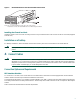
RPS Connector Location on a Cisco Switch (Typical) RATING 100-120/200-240V ~ 2.0A/1.0A 50-60HZ DC INPUTS FOR REMOTE POWER SUPPLY SPECIFIED IN MANUAL. +5V @24A, +12V @1.0A CONSOLE DC INPUT Cisco RPS connector AC power connector RPS 8-Pin Connector Location on a Cisco Router or Concentrator (Typical) Input: 100-240VAC Freq: 50/60 Hz Current: 1.2-0.
Connect the DC-input end of the cable to a Cisco RPS rear-panel connector as shown in Figure 14 or Figure 15.
5 Power Up the Equipment Step 1 If you are using the redundant-with-reboot configuration (not recommended), power up the switch by connecting the AC power cord of the hub or switch to an AC power outlet. Note If you use the redundant-with-reboot configuration, it is important to power up the hub or switch before powering up the Cisco RPS to ensure correct operation. If the Cisco RPS powers up first, the LEDs might not indicate the actual state.
Documentation CD-ROM Cisco documentation and additional literature are available in a Cisco Documentation CD-ROM package, which may have shipped with your product. The Documentation CD-ROM is updated monthly and may be more current than printed documentation. The CD-ROM package is available as a single unit or through an annual subscription. Registered Cisco.com users can order the Documentation CD-ROM (product number DOC-CONDOCCD=) through the online Subscription Store: http://www.cisco.
• Resolve technical issues with online support • Download and test software packages • Order Cisco learning materials and merchandise • Register for online skill assessment, training, and certification programs To obtain customized information and service, you can self-register on Cisco.com at this URL: http://www.cisco.com Technical Assistance Center The Cisco TAC is available to all customers who need technical assistance with a Cisco product, technology, or solution.
8 Obtaining Additional Publications and Information Information about Cisco products, technologies, and network solutions is available from various online and printed sources. • The Cisco Product Catalog describes the networking products offered by Cisco Systems as well as ordering and customer support services. Access the Cisco Product Catalog at this URL: http://www.cisco.com/en/US/products/products_catalog_links_launch.html • Cisco Press publishes a wide range of networking publications.
Corporate Headquarters Cisco Systems, Inc. 170 West Tasman Drive San Jose, CA 95134-1706 USA www.cisco.com Tel: 408 526-4000 800 553-NETS (6387) Fax: 408 526-4100 European Headquarters Cisco Systems International BV Haarlerbergpark Haarlerbergweg 13-19 1101 CH Amsterdam The Netherlands www-europe.cisco.com Tel: 31 0 20 357 1000 Fax: 31 0 20 357 1100 Americas Headquarters Cisco Systems, Inc. 170 West Tasman Drive San Jose, CA 95134-1706 USA www.cisco.