C H A P TER 1 Hardware Description This chapter provides an overview of the Cisco 6200 advanced digital subscriber line access multiplexer (DSLAM) and describes the system’s hardware components.
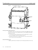
1 Hardware Description 78-5296-02 The Cisco DSL family also includes a Frame Relay IDSL multiplexer, a service selection gateway, the Cisco 605 card, the Cisco 6100 DSLAM, and an ATM switch to aggregate Cisco 6200 traffic. 1.2 Cisco 6200 Chassis This section describes the chassis that houses the Cisco 6200 DSLAM. The Cisco 6200 consists of circuitry and connections that reside within a shelf or chassis that allows modular insertion and removal of the various field-replaceable units (FRUs).
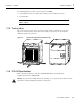
78-5296-02 10/02/98 Hardware Description Figure 1-1 Cisco 6200 Chassis, Front View O I O NTC OC3-SM MPC POWER READY SRVC PROT POWER A C T I V E 1 SLC 8CAP SLC 8CAP SLC 8CAP SLC 8CAP SLC 8CAP SLC 8CAP SLC 8CAP I SLC 8CAP SLC 8CAP SLC 8CAP READY POWER POWER POWER POWER READY POWER ACTIVE READY POWER READY READY POWER READY POWER POWER PRIME READY POWER PRIME PRIME PRIME READY PRIME READY READY SEC PRIME READY SEC SEC PRIME SEC PRIME PRIME SEC PRIME
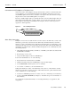
1 Hardware Description Figure 1-2 78-5296-02 Cisco 6200 Chassis, Rear View Dangler cables for subscriber traffic Auxiliary port connector 12686 Alarm relay connector Primary (A) and Secondary (B) H-Buses The backplane’s primary and secondary H-buses (horizontal buses) link the MPC, NTC, and SLCs. In this release, the primary bus carries all traffic. The buses operate at 160 Mbps total throughput.
78-5296-02 10/02/98 Hardware Description 1 Connections to POTS Splitters or Telephone Lines On the inner surface of the backplane, the upper and lower SLC connectors connect the SLC in the corresponding slot (5 to 14) with unshielded twisted pair (UTP) lines. These lines connect to an external POTS splitter, and from there to subscribers over telephone lines. (If a subscriber is using a telephone line for data only, the POTS splitter is not required.
1 Hardware Description 78-5296-02 10/02/98 Auxiliary Port J40, a 9-pin female connector on the Cisco 6200 backplane, is an EIA/TIA-232 (RS-232) serial port connecting to the management processor card (MPC). J40 is an auxiliary craft port that can be used to connect devices such as terminals, modems, or laptop computers to the Cisco 6200. It is accessible from the rear of the chassis. For a pinout list, see Appendix A, “Pin Assignments.
8-5296-02 10/02/98 1 Hardware Description The following fixtures are present on the front panel of each PEM: • • A green LED that comes on to indicate that –48 VDC power is available to the chassis A circuit breaker Note To turn off a Cisco 6200 that has two PEMs, you must flip the circuit breakers on both PEMs to OFF (0). 1.2.5 Cooling Vents The cooling vents are located on the sides, front, and back of the Cisco 6200 chassis, as shown in Figure 1-4.
1 Hardware Description Table 1-1 78-5296-02 10/02/98 Cisco 6200 DSLAM Specifications Specification Description Components 14-slot card compartment Backplane Fan compartment Power module compartment Power input Dual inputs, each –48 VDC Tested voltages: –48V and –57V Tolerance limits: –42V to –57V Maximum input current: 23A Power consumption, fully loaded1 With SLC 8CAPs: 820W With SLC 8DMTs: 892W Dimensions Height: 23.6 in. (60.0 cm) Width: 17.5 in. (44.
78-5296-02 10/02/98 Hardware Description 1 1.3 Network Trunk Cards (NTCs) This section describes the OC-3c and STM-1 network trunk cards (NTCs). The NTC module resides in slot 1 of the Cisco 6200 chassis. 1.3.1 What is the NTC OC-3? The NTC is a service interface module that concentrates the data traffic from all Cisco 6200 subscriber ports and connects the node to a single trunk line from the service-providing ATM network.
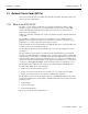
1 Hardware Description Figure 1-5 78-5296-02 10/02/98 NTC OC-3 Application NTC Cisco 6200 Downstream data transfer Optical interface ATM on OC-3c Line module 12688 Upstream data transfer The optical interface performs the optical-to-electrical and electrical-to-optical conversions. Its other tasks include clock recovery, overhead processing, cell delineation, and diagnostic information retrieval.
10/02/98 Hardware Description 1 The fiber optic communication channels in the single-mode OC-3c card (NTC OC3-SM) operate with laser energy, which can be harmful, especially to the eyes. During normal operation this energy is confined to the cable and presents no danger. To avoid injury when you are connecting or disconnecting optical channels, observe these precautions: • Always disconnect the card from the backplane before connecting or disconnecting optical cables.
1 Hardware Description Table 1-3 10/02/98 LEDs on the NTC OC-3 LED Color Condition Indicated POWER Green The module is receiving power. READY Green The NTC is experiencing no problems. Yellow The NTC failed its power-on self test; it has a hardware problem. Refer to Chapter 7, “Troubleshooting.” Off The NTC is either initializing or in test mode. PRIME Green This NTC is active and is using the primary bus. SEC Green This NTC is active and is using the secondary bus.
78-5296-02 10/02/98 Hardware Description 1 1.3.3 NTC OC-3 Specifications Table 1-4 lists the physical and electrical specifications of the NTC. Table 1-4 NTC OC-3 Specifications Specification Description External interface One SONET STS-3c (155 Mbps). Single-mode (intermediate reach) and multimode OC-3c versions available Connector type SC Fiber types • Single mode (up to 15 km) • Multimode (up to 2 km) Average transmitted power • Single mode: –11.
1 Hardware Description 78-5296-02 The NTC STM-1 also transmits upstream data back to the service provider via ATM on the STM-1 physical layer. The Cisco 6200 uses a fixed mapping of permanent virtual channels (PVCs) between trunk and subscriber ports. This means that no configuration of these circuits is required. Thirty-one PVCs link each subscriber port to the trunk port on the NTC. These subscriber traffic PVCs are assigned virtual channel identifiers (VCIs) 33 through 63.
78-5296-02 10/02/98 1 Hardware Description The upstream data transfer unit receives data via a 16-bit parallel input from the internal bus on the node’s backplane. ATM cells are received from a subscriber line card (SLC) channel only after that channel has won access to the upstream data bus from the other contending line channels. The upstream data transfer unit monitors the contention bus to direct inbound data to the optical interface. The downstream data transfer unit inserts data onto the bus.
1 Hardware Description 78-5296-02 Figure 1-8 NTC STM-1 Faceplates NTC NTC STM1-SM STM1-MM POWER POWER READY READY PRIME SEC A C T I V E Card status LEDs PRIME SEC A C T I V E STM-1 port TD A RD Transmit and receive LEDs TD A RD 14271 Reset switch LED Indicators Table 1-5 describes the LEDs on the faceplate of the NTC STM-1.
78-5296-02 10/02/98 Table 1-5 LEDs on the NTC STM-1 LED Color Condition Indicated POWER Green The module is receiving power. READY 1 Hardware Description Green The NTC is experiencing no problems. Yellow The NTC failed its power-on self test; it has a hardware problem. Refer to the Cisco 6200 User Guide for troubleshooting instructions. Off The NTC is either initializing or in test mode. PRIME Green This NTC is active and is using the primary bus.
1 Hardware Description Table 1-6 78-5296-02 NTC STM-1 Specifications Specification Description External interface One SDH STM-1 (155 Mbps). Single-mode (intermediate reach) and multimode STM-1 versions available Connector type SC Fiber types • Single mode (up to 15 km) • Multimode (up to 2 km) Average transmitted power • Single mode: –11.
78-5296-02 10/02/98 Hardware Description 1 The MPC runs a version of Cisco IOS software that is designed for DSL multiplexing. At startup, the MPC loads program software and configuration data from NVRAM, from a server on the network, or from a Flash card in one of its PCMCIA slots. The MPC then provides boot images to the line cards.
1 Hardware Description 78-5296-02 10/02/98 Console Port The console port on the MPC is a serial EIA/TIA-232 port with an RJ-45 connector. See Appendix A, “Pin Assignments,” for pinouts. PCMCIA Slots and Ejection Buttons The MPC provides two slots for PCMCIA Flash memory cards. PCMCIA cards store system software and node configuration information. An ejection button is located beneath each PCMCIA slot; push the button to remove the card.
78-5296-02 10/02/98 Hardware Description 1 1.4.3 MPC Specifications Table 1-8 lists the physical and electrical specifications of the MPC. Table 1-8 MPC Specifications Specification Description External Interfaces • EIA/TIA-232 console port • 10BaseT Ethernet management port Internal Hardware • MIPS RV4640 processor • Galileo GT64011 memory management unit • 16 MB of DRAM • 8MB of Flash memory (to store boot image) • 2 PCMCIA Flash card slots Dimensions (width x height x depth) 1.5 x 15.75 x 9.
1 Hardware Description 78-5296-02 1.5 Subscriber Line Card (SLC) This section describes the CAP and DMT versions of the subscriber line card (SLC). A Cisco 6200 chassis can hold up to 10 SLC modules. Note All the SLCs in a Cisco 6200 chassis should be of the same type. The mixture of CAP and DMT cards in a single chassis is not supported. 1.5.
78-5296-02 10/02/98 Hardware Description 1 In the downstream direction, 11 rates are available ranging from 640 kbps to 7.168 Mbps. In the upstream direction, 9 rates are available, ranging from 91 kbps to 1.088 Mbps. The modems on the CAP SLC train in sequence, first downstream, then upstream. Each modem first acquires the line. Then it tests the signal quality on the line by measuring the signal-to-noise ratio (SNR).
1 Hardware Description 78-5296-02 1.5.2 SLC 8CAP: Physical Description Up to 10 SLCs can be installed in a Cisco 6200 cabinet. The cabinet slots assigned to the SLCs are slot 5 through slot 14. The CAP SLC’s faceplate is labeled SCL 8CAP. The faceplate (Figure 1-11) includes the fixtures discussed in the following paragraphs. Reset Switch The reset switch is recessed behind the faceplate to avoid accidental activation. It is not for customer use.
78-5296-02 10/02/98 Table 1-9 SLC 8CAP LEDs LED Color Condition Indicated POWER Green The SLC is receiving power. READY 1 Hardware Description Green The SLC is experiencing no problems. Yellow At least one port on the SLC is in line test mode. Off The SLC is not communicating with the MPC. This is the case when • The SLC is initializing. • The SLC has a hardware problem.
1 Hardware Description 78-5296-02 1.5.3 SLC 8CAP Specifications Table 1-10 lists the physical and electrical specifications of the CAP SLC (SLC 8CAP).
78-5296-02 10/02/98 Hardware Description 1 1.5.4 What is the SLC 8DMT? The eight-port DMT version of the SLC (SLC 8DMT) is a hot-swappable line module that provides data communication between the Cisco 6200 node and up to eight subscribers. Modems on the SLC 8DMT use discrete multitone (DMT) modulation, a common method for encoding asymmetric digital subscriber line (ADSL) transmissions.
1 Hardware Description 78-5296-02 In the upstream direction, the SLC receives ADSL signals from a POTS splitter and demodulates the DMT-modulated signal. Then the SLC channel contends with the other SLC channels for the upstream data bus. Two priority levels are available. For the first Cisco 6200 release, only UBR service is available. The SLC will ensure fair access among all cells of the same priority.
78-5296-02 10/02/98 • • Hardware Description 1 Number of upstream cells received with invalid header checksum Number of errored seconds (this is the number of seconds in which at least one DMT-layer CRC error, loss of signal, or severely errored frame is observed), both upstream and downstream In addition, the SLC 8DMT reports the following fault indications: • • • • Far end LPR Near end LOS Near end LOF Near end loss of cell delineation (LOCD) 1.5.
1 Hardware Description 78-5296-02 Figure 1-13 SLC 8DMT Faceplate SLC 8DMT POWER READY Card status LEDs PRIME SEC PORTS 0 1 2 Port status LEDs 3 4 5 6 7 13067 Reset switch Reset Switch The reset switch is recessed behind the faceplate to avoid accidental activation. It is not for customer use. LED Indicators Table 1-11 describes the LEDs on the faceplate of the SLC.
78-5296-02 10/02/98 Table 1-11 SLC 8DMT LEDs LED Color Condition Indicated POWER Green The SLC is receiving power. READY 1 Hardware Description Green The SLC is experiencing no problems. Yellow At least one port on the SLC is in line test mode. Off The SLC is not communicating with the MPC. This is the case when • The SLC is initializing. • The SLC has a hardware problem.
1 Hardware Description 78-5296-02 1.5.6 SLC 8DMT Specifications Table 1-12 lists the physical and electrical specifications of the SLC 8DMT. Table 1-12 SLC 8DMT Specifications Specification Description Subscriber ports 8 per card Transmission speeds Downstream: up to 8.