Cisco Unified IP Phone 6921, 6941, 6945, and 6961 Administration Guide for Cisco Unified Communications Manager 8.5 (SCCP and SIP) Americas Headquarters Cisco Systems, Inc. 170 West Tasman Drive San Jose, CA 95134-1706 USA http://www.cisco.
THE SPECIFICATIONS AND INFORMATION REGARDING THE PRODUCTS IN THIS MANUAL ARE SUBJECT TO CHANGE WITHOUT NOTICE. ALL STATEMENTS, INFORMATION, AND RECOMMENDATIONS IN THIS MANUAL ARE BELIEVED TO BE ACCURATE BUT ARE PRESENTED WITHOUT WARRANTY OF ANY KIND, EXPRESS OR IMPLIED. USERS MUST TAKE FULL RESPONSIBILITY FOR THEIR APPLICATION OF ANY PRODUCTS.
CONTENTS Preface ix Overview ix Audience ix Organization ix Related Documentation x Obtaining Documentation, Obtaining Support, and Security Guidelines Document Conventions CHAPTER 1 xi xi An Overview of the Cisco Unified IP Phone 1-1 Understanding the Cisco Unified IP Phones 6921, 6941, 6945, and 6961 What Networking Protocols are Used? 1-2 1-9 What Features are Supported on the Cisco Unified IP Phone 6921, 6941, and 6961? Feature Overview 1-13 Configuring Telephony Features 1-13 Config
Contents Power Outage 2-4 Obtaining Additional Information about Power Understanding Phone Configuration Files 2-5 2-5 Understanding the Phone Startup Process 2-7 Adding Phones to the Cisco Unified CM Database 2-8 Adding Phones with Auto-Registration 2-9 Adding Phones with Auto-Registration and TAPS 2-10 Adding Phones with Cisco Unified CM Administration 2-10 Adding Phones with BAT 2-11 Using Cisco Unified IP Phones with Different Protocols 2-11 Converting a New Phone from SCCP to SIP 2-11 Converting
Contents Editing Values Network Setup Menu 4-3 4-4 IPv4 Setup Menu Options 4-6 Security Configuration Menu 4-9 Trust List Menu 4-9 802.
Contents Call Statistics Screen 7-8 Security Configuration 7-10 CHAPTER 8 Monitoring the Cisco Unified IP Phone Remotely Accessing the Web Page for a Phone 8-2 Disabling and Enabling Web Page Access Device Information Network Setup 9 8-3 8-7 8-9 Streaming Statistics CHAPTER 8-3 8-4 Network Statistics Device Logs 8-1 8-9 Troubleshooting and Maintenance 9-1 Resolving Startup Problems 9-1 Symptom: The Cisco Unified IP Phone Does Not Go Through its Normal Startup Process 9-2 Symptom: The Cis
Contents APPENDIX A Providing Information to Users Via a Website A-1 How Users Obtain Support for the Cisco Unified IP Phone Giving Users Access to the User Options Web Pages A-1 A-1 How Users Subscribe to Services and Configure Phone Features How Users Access a Voice Messaging System A-2 A-2 How Users Configure Personal Directory Entries A-3 Installing and Configuring the Cisco Unified IP Phone Address Book Synchronizer APPENDIX B Supporting International Users B-1 Installing the Cisco Unif
Contents APPENDIX G Feature Support by Protocol for the Cisco Unified IP Phone 6921, 6941, 6945, and 6961 G-1 INDEX viii Cisco Unified IP Phone 6921, 6941, 6945, and 6961 Administration Guide for Cisco Unified Communications Manager 8.
Preface Overview Cisco Unified IP Phone 6921, 6941, 6945, and 6961 Administration Guide for Cisco Unified Communications Manager 8.5 (SCCP and SIP) provides the information you need to understand, install, configure, manage, and troubleshoot the phones on a Voice-over-IP (VoIP) network.
Chapter 4, “Configuring Settings on the Cisco Unified IP Phone” Describes how to configure network settings, verify status, and make global changes to the Cisco Unified IP Phone. Chapter 5, “Configuring Features, Templates, Services, and Users” Provides an overview of procedures for configuring telephony features, configuring directories, configuring phone button and softkey templates, setting up services, and adding users to Cisco Unified Communications Manager.
• Regulatory Compliance and Safety Information for Cisco Unified IP Phones Cisco Unified Communications Manager Administration Related publications are available at the following URL: http://www.cisco.com/en/US/products/sw/voicesw/ps556/tsd_products_support_series_home.html Cisco Unified Communications Manager Business Edition Related publications are available at the following URL: http://www.cisco.com/en/US/products/ps7273/tsd_products_support_series_home.
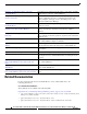
Convention Description string A nonquoted set of characters. Do not use quotation marks around the string or the string will include the quotation marks. screen font boldface screen Note Caution Terminal sessions and information the system displays are in screen font. font Information you must enter is in boldface screen font. italic screen font Arguments for which you supply values are in italic screen font.
CH A P T E R 1 An Overview of the Cisco Unified IP Phone The Cisco Unified IP Phones 6921, 6941, 6945, and 6961 provide voice communication over an IP network. The Cisco Unified IP Phone functions much like a digital business phone, allowing you to place and receive phone calls and to access features such as mute, hold, transfer, speed dial, call forward, and more.
Chapter Understanding the Cisco Unified IP Phones 6921, 6941, 6945, and 6961 Understanding the Cisco Unified IP Phones 6921, 6941, 6945, and 6961 Figure 1-1 shows the main components of the Cisco Unified IP Phone 6921. Figure 1-1 Cisco Unified IP Phone 6921 1 2 17 3 16 4 15 5 14 6 7 1 /.@ 2 ABC DEF 3 1 6 2 8 4 13 GHI 7 PQRS 5 JKL 8 TUV MNO 9 9 WXYZ 0 192525 10 12 11 Table 1-1 describes the buttons on the Cisco Unified IP Phone 6921.
Chapter Understanding the Cisco Unified IP Phones 6921, 6941, 6945, and 6961 Table 1-1 Features on the Cisco Unified IP Phone 6921 (continued) 5 Conference button Creates a conference call. 6 Hold button 7 Navigation bar and The Navigation bar allows you to scroll through menus and highlight items. Select button When phone is on-hook, displays phone numbers from your Placed Call listings (up arrow) or your speed dials (down arrow). Places an active call on hold.
Chapter Understanding the Cisco Unified IP Phones 6921, 6941, 6945, and 6961 Table 1-1 Features on the Cisco Unified IP Phone 6921 (continued) 16 Contacts button Opens/closes the Directories and the Subscribed phone services menus. Use it to access personal and corporate directories. 17 Handset Phone handset. Figure 1-2 shows the main components of the Cisco Unified IP Phone 6941 and 6945.
Chapter Understanding the Cisco Unified IP Phones 6921, 6941, 6945, and 6961 Table 1-2 3 Features on the Cisco Unified IP Phone 6941 and 6945 Programmable feature buttons Depending on the configuration, programmable feature buttons provide access to: • Phone lines and intercom lines • Speed-dial numbers (speed-dial buttons, including the line status speed-dial features) • Web-based services (for example, a Personal Address Book button) • Call features (for example, a Privacy button) Buttons ill
Chapter Understanding the Cisco Unified IP Phones 6921, 6941, 6945, and 6961 Table 1-2 1-6 Features on the Cisco Unified IP Phone 6941 and 6945 13 Volume button Controls the handset, headset, and speakerphone volume (off-hook) and the ringer volume (on-hook). 14 Messages button Auto-dials your voice message service (varies by service). 15 Applications button Opens/closes the Applications menu.
Chapter Understanding the Cisco Unified IP Phones 6921, 6941, 6945, and 6961 Figure 1-3 shows the main components of the Cisco Unified IP Phone 6961. Figure 1-3 Cisco Unified IP Phone 6961 1 2 17 3 16 4 15 5 14 6 7 1 /.@ 4 13 GHI 7 PQRS 2 ABC 5 JKL 8 TUV 8 3 DEF 6 MNO 9 9 WXYZ 0 192527 10 12 11 Table 1-3 describes the buttons on the Cisco Unified IP Phone 6961.
Chapter Understanding the Cisco Unified IP Phones 6921, 6941, 6945, and 6961 Table 1-3 Features on the Cisco Unified IP Phone 6961 6 Hold button 7 Navigation bar and The Navigation bar allows you to scroll through menus and highlight items. select button When phone is on-hook, displays phone numbers from your Placed Call listings (up arrow) or your speed dials (down arrow). Places an active call on hold. The Select button allows you to select a highlighted item.
Chapter What Networking Protocols are Used? Table 1-3 Features on the Cisco Unified IP Phone 6961 16 Contacts button Opens/closes the Directories menu. Use it to access personal and corporate directories. 17 HandSet Phone handset. What Networking Protocols are Used? Cisco Unified IP Phones support several industry-standard and Cisco networking protocols required for voice communication.
Chapter What Networking Protocols are Used? Table 1-4 Supported Networking Protocols on the Cisco Unified IP Phone (continued) Networking Protocol Purpose Usage Notes Dynamic Host Configuration Protocol (DHCP) DHCP dynamically allocates and assigns an IP address to network devices. DHCP is enabled by default. If disabled, you must manually configure the IP address, subnet mask, gateway, and a TFTP server on each phone locally.
Chapter What Networking Protocols are Used? Table 1-4 Supported Networking Protocols on the Cisco Unified IP Phone (continued) Networking Protocol Purpose Usage Notes Link Layer Discovery Protocol-Media Endpoint Devices (LLDP-MED) LLDP-MED is an extension of the LLDP standard developed for voice products.
Chapter What Features are Supported on the Cisco Unified IP Phone 6921, 6941, and 6961? Table 1-4 Supported Networking Protocols on the Cisco Unified IP Phone (continued) Networking Protocol Purpose Usage Notes Transport Layer Security (TLS) TLS is a standard protocol for securing and authenticating communications. When security is implemented, Cisco Unified IP Phones use the TLS protocol when securely registering with Cisco Unified CM.
Chapter What Features are Supported on the Cisco Unified IP Phone 6921, 6941, and 6961? Feature Overview Cisco Unified IP Phones provide traditional telephony functionality, such as call forwarding and transferring, redialing, speed dialing, conference calling, and voice messaging system access. Cisco Unified IP phones also provide a variety of other features.
Chapter Understanding Security Features for Cisco Unified IP Phones Configuring Network Parameters Using the Cisco Unified IP Phone You can configure parameters such as DHCP, TFTP, and IP settings on the phone itself. You can also obtain statistics about a current call or firmware versions on the phone.
Chapter Understanding Security Features for Cisco Unified IP Phones Table 1-5 Cisco Unified IP Phone and Cisco Unified CM Security Topics Topic Reference Detailed explanation of security, including set up, configuration, and troubleshooting information for Cisco Unified CM and Cisco Unified IP Phones Refer to the Troubleshooting Guide for Cisco Unified Communications Manager Security features supported on the Cisco Unified See the “Overview of Supported Security Features” section on page 1-16 IP Phon
Chapter Understanding Security Features for Cisco Unified IP Phones Table 1-5 Cisco Unified IP Phone and Cisco Unified CM Security Topics (continued) Topic Reference Resetting or restoring the phone See the “Resetting or Restoring the Cisco Unified IP Phone” section on page 9-12 802.1X Authentication for Cisco Unified IP Phones See these sections: • “Supporting 802.
Chapter Understanding Security Features for Cisco Unified IP Phones Table 1-6 Overview of Security Features (continued) Feature Description Device authentication Occurs between the Cisco Unified CM server and the phone when each entity accepts the certificate of the other entity. Determines whether a secure connection between the phone and a Cisco Unified CM should occur; and, if necessary, creates a secure signaling path between the entities by using TLS protocol.
Chapter Understanding Security Features for Cisco Unified IP Phones Table 1-6 Overview of Security Features (continued) Feature Description Phone hardening Additional security options, which you control from Cisco Unified CM Administration: • Disabling PC port • Disabling PC Voice VLAN access • Disabling access to web pages for a phone Note 802.
Chapter Understanding Security Features for Cisco Unified IP Phones In a secure call, a security tone plays at the beginning of a call to indicate that the other connected phone is also receiving and transmitting encrypted audio and video (if video is involved). If your call is connected to a non-protected phone, the security tone does not play. Note Secured calling is supported for connections between two phones only.
Chapter Understanding Security Features for Cisco Unified IP Phones Note Protected calling is supported for conversations between two phones. Some features, such as conference calling, shared lines, Cisco Extension Mobility, and Join Across Lines are not available when protected calling is configured.
Chapter Understanding Security Features for Cisco Unified IP Phones Supporting 802.1X Authentication on Cisco Unified IP Phones These sections provide information about 802.
Chapter Overview of Configuring and Installing Cisco Unified IP Phones • Configure PC Port—The 802.1X standard does not take into account the use of VLANs and thus recommends that only a single device should be authenticated to a specific switch port. However, some switches (including Cisco Catalyst switches) support multi-domain authentication. The switch configuration determines whether you can connect a PC to the phone’s PC port.
Chapter Overview of Configuring and Installing Cisco Unified IP Phones The following topics provide an overview of procedures for adding Cisco Unified IP Phones to your network: • Configuring Cisco Unified IP Phones in Cisco Unified CM, page 1-23 • Installing Cisco Unified IP Phones, page 1-27 Configuring Cisco Unified IP Phones in Cisco Unified CM To add phones to the Cisco Unified CM database, you can use: • Auto-registration • Cisco Unified CM Administration • Bulk Administration Tool (BAT) •
Chapter Overview of Configuring and Installing Cisco Unified IP Phones Checklist for Configuring the Cisco Unified IP Phones 6921, 6941, 6945, and 6961 in Cisco Unified CM Table 1-9 provides an overview and checklist of configuration tasks for the Cisco Unified IP Phones 6921, 6941, 6945, and 6961 in Cisco Unified CM Administration. The list presents a suggested order to guide you through the phone configuration process. Some tasks are optional, depending on your system and user needs.
Chapter Overview of Configuring and Installing Cisco Unified IP Phones Table 1-9 Task 4. Checklist for Configuring the Cisco Unified IP Phones 6921, 6941, 6945, and 6961 in Cisco Unified CM Purpose For More Information Add and configure the phone by completing the required fields in the Phone Configuration window. Required fields are indicated by an asterisk (*) next to the field name; for example, MAC address and device pool.
Chapter Overview of Configuring and Installing Cisco Unified IP Phones Table 1-9 Checklist for Configuring the Cisco Unified IP Phones 6921, 6941, 6945, and 6961 in Cisco Unified CM Task Purpose For More Information 10. Add user information by configuring required fields. Required fields are indicated by an asterisk (*); for example, User ID and last name. For more information, see the Cisco Unified Communications Manager Administration Guide, End User Configuration.
Chapter Overview of Configuring and Installing Cisco Unified IP Phones Installing Cisco Unified IP Phones After you have added the phones to the Cisco Unified CM database, you can complete the phone installation. You (or the phone users) can install the phone at the users’s location. The Cisco Unified IP Phone Installation Guide, which is provided on the cisco.com web site, provides directions for connecting the phone handset, cables, and other accessories.
Chapter Overview of Configuring and Installing Cisco Unified IP Phones Table 1-10 Task 4. Installation Checklist for the Cisco Unified IP Phone 6921, 6941, and 6961 (continued) Purpose For More Information If you are configuring the network settings on the phone, you can set up an IP address for the phone by either using DHCP or manually entering an IP address. See the “Configuring Startup Network Settings” section on page 3-15. See the “Network Setup Menu” section on page 4-4.
Chapter Terminology Differences Terminology Differences Table 1-11 highlights some of the important differences in terminology that is used in these documents: • Cisco Unified IP Phone 6921, 6941, and 6961 User Guide for Cisco Unified Communications Manager 8.5 (SCCP and SIP) • Cisco Unified IP Phone 6921, 6941, 6945, and 6961 Administration Guide for Cisco Unified Communications Manager 8.
Chapter Terminology Differences 1-30 Cisco Unified IP Phone 6921, 6941, 6945, and 6961 Administration Guide for Cisco Unified Communications Manager 8.
CH A P T E R 2 Preparing to Install the Cisco Unified IP Phone on Your Network Cisco Unified IP phones enable you to communicate by using voice over a data network. To provide this capability, the IP Phones depend upon and interact with several other key Cisco Unified IP Telephony components, including Cisco Unified Communications Manager (Cisco Unified CM).
Chapter Understanding Interactions with Other Cisco Unified IP Telephony Products Understanding How the Cisco Unified IP Phone Interacts with Cisco Unified CM Cisco Unified CM is an open and industry-standard call processing system. Cisco Unified CM software sets up and tears down calls between phones, integrating traditional PBX functionality with the corporate IP network.
Chapter Providing Power to the Cisco Unified IP Phone You can resolve these issues by isolating the voice traffic onto a separate VLAN.
Chapter Providing Power to the Cisco Unified IP Phone Power Guidelines Table 2-1 provides guidelines for powering the Cisco Unified IP Phone 6921, 6941, and 6961. Table 2-1 Guidelines for Powering the Cisco Unified IP Phone 6921, 6941, and 6961 Power Type Guidelines External power—Provided through the CP-PWR-CUBE-3 external power supply. The Cisco Unified IP Phone 6921, 6941, and 6961 use the CP-PWR-CUBE-3 power supply. External power—Provided through the Cisco Unified IP Phone Power Injector.
Chapter Understanding Phone Configuration Files Obtaining Additional Information about Power For related information about power, refer to the documents shown in Table 2-2.
Chapter Understanding Phone Configuration Files If you configure security-related settings in Cisco Unified CM Administration, the phone configuration file will contain sensitive information. To ensure the privacy of a configuration file, you must configure it for encryption. For detailed information, refer to the “Configuring Encrypted Phone Configuration Files” chapter in Cisco Unified Communications Manager Security Guide.
Chapter Understanding the Phone Startup Process Understanding the Phone Startup Process When connecting to the VoIP network, the Cisco Unified IP Phone 6921, 6941, and 6961 go through a standard startup process that is described in Table 2-3. Depending on your specific network setup, not all of these steps may occur on your Cisco Unified IP Phone. Table 2-3 Task 1. 2.
Chapter Adding Phones to the Cisco Unified CM Database Table 2-3 Task 7. Cisco Unified IP Phone Startup Process (continued) Purpose Related Topics Requesting the Configuration File • The TFTP server has configuration files, which define parameters for connecting to Cisco Unified CM and other information for the phone. Adding Phones to the Cisco Unified CM Database, page 2-8. • Resolving Startup Problems, page 9-1. Contacting Cisco Unified CM 8. Resolving Startup Problems, page 9-1.
Chapter Adding Phones to the Cisco Unified CM Database Table 2-4 provides an overview of these methods for adding phones to the Cisco Unified CM database. Table 2-4 Methods for Adding Phones to the Cisco Unified CM Database Method Requires MAC Address? Auto-registration No Notes • Results in automatic assignment of directory numbers • Not available when security or encryption is enabled Note Auto-registration is disabled when security is enabled on Cisco Unified CM.
Chapter Adding Phones to the Cisco Unified CM Database Note When you configure the cluster for mixed mode through the Cisco CTL client, auto-registration is automatically disabled. When you configure the cluster for non-secure mode through the Cisco CTL client, auto-registration is automatically enabled.
Chapter Using Cisco Unified IP Phones with Different Protocols For information about determining a MAC address, see the “Determining the MAC Address for a Cisco Unified IP Phone” section on page 2-13. After you have collected MAC addresses, in Cisco Unified CM Administration, choose Device > Phone and click Add New to begin.
Chapter Using Cisco Unified IP Phones with Different Protocols Procedure Step 1 Take one of these actions: • To auto-register the phone, set the Auto Registration Phone Protocol parameter in Cisco Unified Communications Manager Administration to SIP. • To provision the phone using the Bulk Administration Tool (BAT), choose the appropriate phone model and choose SIP from the BAT.
Chapter Determining the MAC Address for a Cisco Unified IP Phone Determining the MAC Address for a Cisco Unified IP Phone Several procedures described in this manual require you to determine the MAC address of a Cisco Unified IP Phone. You can determine a phone’s MAC address in these ways: • From the phone, press the Applications button and select Phone Information and look at the MAC Address field. • Look at the MAC label on the back of the phone.
Chapter Determining the MAC Address for a Cisco Unified IP Phone 2-14 Cisco Unified IP Phone 6921, 6941, 6945, and 6961 Administration Guide for Cisco Unified Communications Manager 8.
CH A P T E R 3 Setting Up the Cisco Unified IP Phone This chapter includes the following topics, which help you install the Cisco Unified IP Phone on an IP telephony network: Note • Before You Begin, page 3-1 • Understanding the Cisco Unified IP Phones 6921, 6941, 6945, and 6961 Components, page 3-2 • Installing the Cisco Unified IP Phone, page 3-5 • Reducing Power Consumption on the Phone, page 3-9 • Footstand, page 3-9 • Verifying the Phone Startup Process, page 3-14 • Configuring Startup
Chapter Understanding the Cisco Unified IP Phones 6921, 6941, 6945, and 6961 Components Note The Cisco Unified IP Phone displays the date and time from Cisco Unified CM. If the Cisco Unified CM server is located in a different time zone than the phones, the phones will not display the correct local time. Cisco Unified Communications Manager Configuration The Cisco Unified IP Phone requires Cisco Unified CM to handle call processing.
Chapter Understanding the Cisco Unified IP Phones 6921, 6941, 6945, and 6961 Components Each port supports 10/100 Mbps half- or full-duplex connections to external devices. Cisco Unified IP Phone 6945 also supports 1000 Mbps full-duplex connections to external devices.You can use either Category 3/5/5e cabling for 10-Mbps connections, but you must use Category 5/5e for 100 or 1000 Mbps connections. Use the SW network port to connect the phone to the network.
Chapter Understanding the Cisco Unified IP Phones 6921, 6941, 6945, and 6961 Components Audio Quality Beyond its physical, mechanical and technical performance, the audio portion of a headset must sound good to the user and to the party on the far end. Sound quality is subjective and Cisco cannot guarantee the performance of any headsets. However, a variety of headsets from leading headset manufacturers have been reported to perform well with Cisco Unified IP Phones. See manufacturer’s sites for details.
Chapter Installing the Cisco Unified IP Phone Installing the Cisco Unified IP Phone You must connect the Cisco Unified IP Phone to the network and to a power source before using it. See Figure 3-1 shows the connections for Cisco Unified IP phones 6921 and 6941, Figure 3-3 shows the connections for a Cisco Unified IP Phone 6945, and Figure 3-2 shows the connections for a Cisco Unified IP Phone 6961. Note Before you install a phone, even if it is new, upgrade the phone to the current firmware image.
Chapter Installing the Cisco Unified IP Phone Figure 3-1 Cisco Unified IP Phone 6921 and 6941 Cable Connections 1 3 7 2 6 4 3-6 192762 5 Cisco Unified IP Phone 6921, 6941, 6945, and 6961 Administration Guide for Cisco Unified Communications Manager 8.
Chapter Installing the Cisco Unified IP Phone Figure 3-2 Cisco Unified IP Phone 6961 Cable Connections 1 3 7 2 6 192617 5 4 1 DC adaptor port (DC48V) 5 Access port (10/100 PC) connection 2 AC-to-DC power supply (optional) 6 Handset connection 3 AC power wall plus (optional) 7 Analog headset connection (optional) 4 Network port (10/100 SW) connection. IEEE 802.
Chapter Installing the Cisco Unified IP Phone Figure 3-3 Cisco Unified IP Phone 6945 Cable Connections 1 3 8 2 7 6 199282 5 4 1 DC adaptor port (DC48V). 5 Access port (10/100/1000 PC) connection. 2 AC-to-DC power supply (optional). 6 Auxiliary port. 3 AC power wall plug (optional). 7 Handset connection. 4 Network port (10/100/1000 SW) connection. IEEE 802.3af power enabled. 8 Analog headset connection (optional).
Chapter Reducing Power Consumption on the Phone Reducing Power Consumption on the Phone You can reduce the amount of energy that the Cisco Unified IP Phone 6921, 6941, 6945, and 6961 consumes by scheduling when the phone goes into power save mode. In power save mode, the backlight on the screen is not lit when the phone is not in use. The phone remains in power save mode for the scheduled duration or until the user lifts the handset or presses any button.
Chapter Footstand Figure 3-4 Cisco Unified IP Phone 6921 and 6941 2 194407 1 1 3-10 Footstand slots for a higher viewing angle 2 Footstand slots for a lower viewing angle Cisco Unified IP Phone 6921, 6941, 6945, and 6961 Administration Guide for Cisco Unified Communications Manager 8.
Chapter Footstand Figure 3-5 Cisco Unified IP Phone 6945 2 199283 1 1 Footstand slots for a higher viewing angle 2 Footstand slots for a lower viewing angle Cisco Unified IP Phone 6921, 6941, 6945, and 6961 Administration Guide for Cisco Unified Communications Manager 8.
Chapter Footstand Figure 3-6 Cisco Unified IP Phone 6961 2 1 194406 CISCO 1 3-12 Footstand slots for a higher viewing angle 2 Footstand slots for a lower viewing angle Cisco Unified IP Phone 6921, 6941, 6945, and 6961 Administration Guide for Cisco Unified Communications Manager 8.
Chapter Footstand 195159 Higher Viewing Angle Cisco Unified IP Phone 6921, 6941, 6945, and 6961 Administration Guide for Cisco Unified Communications Manager 8.
Chapter Mounting the Phone to the Wall 195160 Lower Viewing Angle Mounting the Phone to the Wall You can mount the Cisco Unified IP Phone on the wall by using special brackets available in a Cisco Unified IP Phone wall mount kit. For information on installing the wall mount kit, see Appendix E, “Installing the Wall Mount Kit for the Cisco Unified IP Phones 6921, 6941, 6945, and 6961” or Appendix F, “Cisco Unified IP Phone Non-Lockable Wall Mount.
Chapter Configuring Startup Network Settings Table 3-2 LED Diagnostic Status Hardware Test MWI Hold Mute Speaker Power is Ready On On On On Flash is Accessible — On On On RAM Test Successful — — On On Ethernet Test Successful — — — On 2. The screen displays the Cisco Systems, Inc., logo screen. 3. These messages appear as the phone starts up. – Phone not registered 4.
Chapter Configuring Security on the Cisco Unified IP Phone Before You Begin Make sure that the appropriate Cisco Unified CM and the Certificate Authority Proxy Function (CAPF) security configurations are complete: • The CTL file should have a CAPF certificate. • On Cisco Unified Communications Operating System Administration, verify that the CAPF certificate has been installed. • The CAPF is running and configured. Refer to Cisco Unified Communications Manager Security Guide for more information.
CH A P T E R 4 Configuring Settings on the Cisco Unified IP Phone The Cisco Unified IP Phone includes many configurable network settings that you may need to modify before the phone is functional for your users. You can access these settings, and change some of them, through menus on the phone. Settings that are display-only on the phone are configured in Cisco Unified CM Administration.
Chapter Configuration Menus on the Cisco Unified IP Phone • IPv4 Setup Menu Options, page 4-6 Displaying a Configuration Menu To display a configuration menu, perform the following steps. Note You can control whether a phone has access to the Settings menu or to options on this menu by using the Settings Access field in the Cisco Unified CM Administration Phone Configuration window. The Settings Access field accepts these values: • Enabled—Allows access to the Settings menu.
Chapter Configuration Menus on the Cisco Unified IP Phone • Network Setup Menu, page 4-4 • IPv4 Setup Menu Options, page 4-6 Unlocking and Locking Options You can apply a password to the phone so that no changes can be made to the administrative options on the phone without the password being entered on the Admin Settings phone screen.
Chapter Network Setup Menu Network Setup Menu The Network Setup menu provides options for viewing and making a variety of network settings. Table 4-1 describes these options and, where applicable, explains how to change them. For information about how to access the Network Setup menu, see the “Displaying a Configuration Menu” section on page 4-2. For information about the keys you can use to edit options, see the “Editing Values” section on page 4-3.
Chapter Network Setup Menu Table 4-1 Network Setup Menu Options (continued) Option Description PC VLAN Allows the phone to interoperate with 3rd party switches that do not support a voice VLAN. The Admin VLAN ID option must be set before you can change this option. SW Port Setup Speed and duplex of the network port. Valid values: • Auto Negotiate • 1000 Full—1000-BaseT/full duplex (Supported only for Cisco Unified IP Phone 6945.
Chapter IPv4 Setup Menu Options Table 4-1 Network Setup Menu Options (continued) Option Description PC Port Setup Speed and duplex of the access port. Valid values: • Auto Negotiate • 1000 Full—1000-BaseT/full duplex (Supported only for Cisco Unified IP Phone 6945.
Chapter IPv4 Setup Menu Options Table 4-2 describes the IPv4 Setup menu options. For information about the keys you can use to edit options, see the “Editing Values” section on page 4-3. Table 4-2 IPv4 Setup Menu Options Option Description To Change DHCP Indicates whether the phone has DHCP enabled or disabled. Scroll to the DHCP option, press the Edit softkey, then press either the No softkey to disable DHCP, or press the Yes softkey to enable DHCP.
Chapter IPv4 Setup Menu Options Table 4-2 IPv4 Setup Menu Options (continued) Option Description To Change Alternate TFTP Indicates whether the phone is using an alternative TFTP server. Scroll to the Alternate TFTP option and press the Yes softkey if the phone should use an alternative TFTP server; press the No softkey if the phone should not use an alternative TFTP server. TFTP Server 1 Primary Trivial File Transfer Protocol (TFTP) server used by the phone.
Chapter Security Configuration Menu Security Configuration Menu The Security Configuration menu provides information about various security settings. It provides access to the Trust List File screen and the 802.1x authentication. Table 4-3 describes the options in this menu. Table 4-3 Security Menu Settings Option Description To Change Security Mode Displays the security mode that is set for the phone. From Cisco Unified CM Administration, choose Device > Phone > Phone Configuration.
Chapter Security Configuration Menu Table 4-5 802.1X Authentication Settings Option Description Device Authentication Determines whether 802.1X authentication is enabled: • • EAP-MD5 Enabled—Phone uses 802.1X authentication to request network access. Disabled—Default setting in which the phone uses CDP to acquire VLAN and network access.
CH A P T E R 5 Configuring Features, Templates, Services, and Users After you install Cisco Unified IP Phones in your network, configure their network settings, and add them to Cisco Unified CM, you must use the Cisco Unified Communications Manager Administration application to configure telephony features, optionally modify phone templates, set up services, and assign users. This chapter provides an overview of these configuration and setup procedures.
Chapter Telephony Features Available for the Cisco Unified IP Phone For information about using most of these features on the phone, refer to Cisco Unified IP Phone 6921, 6941, and 6961 User Guide for Cisco Unified Communications Manager 8.5. Note Cisco Unified Communications Manager Administration also provides several service parameters that you can use to configure various telephony functions.
Chapter Telephony Features Available for the Cisco Unified IP Phone Table 5-1 Telephony Features for the Cisco Unified IP Phone (continued) Feature Description Audible Message Waiting Indicator (AMWI) A stutter tone from the handset, headset, or For more information, see the Cisco Unified speakerphone indicates that a user has one or more Communications Manager System Guide, new voice messages on a line. Cisco Unified IP Phone. Note Configuration Reference The stutter tone is line-specific.
Chapter Telephony Features Available for the Cisco Unified IP Phone Table 5-1 Telephony Features for the Cisco Unified IP Phone (continued) Feature Description Configuration Reference Busy Lamp Field (BLF) Pickup Provides enhancements to BLF speed dial. Allows For more information, see the Cisco Unified you to configure a Directory Number (DN) that a Communications Manager Features and user can monitor for incoming calls. When the DN Services Guide, Call Pickup.
Chapter Telephony Features Available for the Cisco Unified IP Phone Table 5-1 Telephony Features for the Cisco Unified IP Phone (continued) Feature Description Configuration Reference Call forward configurable display Allows you to specify information that appears on For more information, see the following: a phone when a call is forwarded.
Chapter Telephony Features Available for the Cisco Unified IP Phone Table 5-1 Telephony Features for the Cisco Unified IP Phone (continued) Feature Description Caller ID Caller identification such as a phone number, For more information, refer to: name, or other descriptive text appear on the phone • Cisco Unified Communications Manager display. Administration Guide, Cisco Unified IP Phone Configuration.
Chapter Telephony Features Available for the Cisco Unified IP Phone Table 5-1 Telephony Features for the Cisco Unified IP Phone (continued) Feature Description Configuration Reference Cisco Extension Enables a user configured in one cluster to log into For more information, see the Cisco Unified Mobility Cross Cluster a Cisco Unified IP Phone in another cluster.
Chapter Telephony Features Available for the Cisco Unified IP Phone Table 5-1 Telephony Features for the Cisco Unified IP Phone (continued) Feature Description Configuration Reference Directed Call Park Allows a user to transfer an active call to an available directed call park number that the user dials or speed dials. For more information, see the Cisco Unified Communications Manager Features and Services Guide, Call Park and Directed Call Park.
Chapter Telephony Features Available for the Cisco Unified IP Phone Table 5-1 Telephony Features for the Cisco Unified IP Phone (continued) Feature Description Configuration Reference Fast Dial Service Allows a user to enter a Fast Dial code to place a call. Fast Dial codes can be assigned to phone numbers or Personal Address Book entries. (See “Services” in this table.) For more information, see Modifying a Phone Button Template for Personal Address Book or Speed Dials, page 5-18.
Chapter Telephony Features Available for the Cisco Unified IP Phone Table 5-1 Telephony Features for the Cisco Unified IP Phone (continued) Feature Description Configuration Reference Intercom Allows users to place and receive intercom calls using programmable phone buttons. You can configure intercom line buttons to: For more information, see the Cisco Unified Communications Manager Feature and Services Guide, Intercom. • Directly dial a specific intercom extension.
Chapter Telephony Features Available for the Cisco Unified IP Phone Table 5-1 Telephony Features for the Cisco Unified IP Phone (continued) Feature Description Configuration Reference For more information: Log out of hunt groups Allows users to log out of a hunt group and temporarily block calls from ringing their phone • See the “Configuring Softkey Templates” when they are not available to take calls. Logging section on page 5-19.
Chapter Telephony Features Available for the Cisco Unified IP Phone Table 5-1 Telephony Features for the Cisco Unified IP Phone (continued) Feature Description Configuration Reference Onhook Dialing Allows a user to dial a number without going off For more information, refer to the Cisco hook. The user can then either pick up the handset Unified IP Phone 6921, 6941, 6945, and 6961 or press the Dial softkey. User Guide, “Basic Call Handling.
Chapter Telephony Features Available for the Cisco Unified IP Phone Table 5-1 Telephony Features for the Cisco Unified IP Phone (continued) Feature Description Configuration Reference Reroute Direct Calls to Reroutes a direct call to users’ mobile phone to the For more information, see the Cisco Unified Remote Destination to enterprise number (desk phone). For an incoming Communications Manager Features and Services Guide, Cisco Unified Mobility.
Chapter Telephony Features Available for the Cisco Unified IP Phone Table 5-1 Telephony Features for the Cisco Unified IP Phone (continued) Feature Description Configuration Reference Services URL button Allows users to access services from a programmable button rather than by using the Services menu on a phone. For more information, see the following: • Cisco Unified Communications Manager Administration Guide, Cisco Unified IP Phone Configuration.
Chapter Telephony Features Available for the Cisco Unified IP Phone Table 5-1 Telephony Features for the Cisco Unified IP Phone (continued) Feature Description Configuration Reference Time-of-Day Routing Restricts access to specified telephony features by For more information refer to: time period. • Cisco Unified Communications Manager Administration Guide, Time Period Configuration. • Cisco Unified Communications Manager System Guide, Time-of-Day Routing.
Chapter Configuring Corporate and Personal Directories • To configure the policy for all phones on the system, choose System > Enterprise Phone Configurations from Cisco Unified Communications Manager Administration. • To configure the policy to a group of phones, choose Device > Device Settings > Common Phone Profile from Cisco Unified Communications Manager Administration.
Chapter Modifying Phone Button Templates • Personal Address Book (PAB) • Speed Dials • Address Book Synchronization Tool (TABSynch) Users can access Personal Directory features by these methods: • From a web browser—Users can access the PAB and Speed Dials features from the Cisco Unified Communications Manager User Options web pages • From the Cisco Unified IP Phone—Choose Contacts to search the corporate directory or the user’s personal directory.
Chapter Modifying Phone Button Templates Modifying a Phone Button Template for Personal Address Book or Speed Dials You can modify a phone button template to associate a service URL with a line button. Doing so enables users to have single-button access to the PAB and Speed Dials. Before you modify the phone button template, you must configure PAB or Speed Dials as an IP phone service.
Chapter Configuring Softkey Templates Step 3 Select the phone model. Step 4 Click Copy, enter a name for the new template, and then click Save. The Phone Button Template Configuration window opens. Step 5 Identify the button you would like to assign, and select Service URL from the Features drop-down list box associated with the line. Step 6 Click Save to create a new phone button template using the service URL. Step 7 Choose Device > Phone and open the Phone Configuration window for the phone.
Chapter Configuring Softkey Templates Table 5-2 Configurable Softkeys Feature Supported as a softkey on Cisco Configurable Softkeys in the Unified IP Phone 6921, 6941, 6945, and Softkey Template 6961 Configuration Notes Answer Answer (Answer) Yes — Barge Barge (Barge) No — Call Back Call Back (CallBack) Yes — Call Forward All Forward All (cfwdAll) Yes Phone displays Fwd ALL or Fwd Off.
Chapter Setting Up Services Table 5-2 Configurable Softkeys (continued) Feature Supported as a softkey on Cisco Configurable Softkeys in the Unified IP Phone 6921, 6941, 6945, and Softkey Template 6961 Configuration Notes Transfer Direct Transfer (DirTrfr) Transfer is a dedicated button. No Configure transfer (Direct Transfer policy) in the Product Specific Configuration Layout section in Phone Configuration.
Chapter Adding Users to Cisco Unified Communications Manager Adding Users to Cisco Unified Communications Manager Adding users to Cisco Unified Communications Manager allows you to display and maintain information about users and allows each user to perform these tasks: • Access the corporate directory and other customized directories from a Cisco Unified IP Phone. • Create a personal directory. • Set up speed dial and call forwarding numbers.
Chapter Managing the User Options Web Pages Procedure Step 1 From Cisco Unified Communications Manager Administration, choose User Management > User Groups. The Find and List Users window displays. Step 2 Enter the appropriate search criteria and click Find. Step 3 Click the Standard CCM End Users link. The User Group Configuration page for the Standard CCM End Users displays. Step 4 Click Add End Users to Group. The Find and List Users window displays.
Chapter Managing the User Options Web Pages Make sure to provide end users with the following information about the User Options web pages: The URL required to access the application. This URL is: http:///ccmuser/, where server_name is the host name of the Cisco Unified Communications Manager. • A user ID and default password are needed to access the application.
Chapter Configuring the Phone to Support Call Waiting Configuring the Phone to Support Call Waiting The Cisco Unified IP phones 6921, 6941, 6945, and 6961 support one call per line. Cisco Unified CM sets the Maximum Number of Calls (MNC) per line, and Busy Trigger (BT) per line attributes to 1 and these fields cannot be changed, As a result, the line appears to be busy to a second incoming call when there is an active call present on the line.
Chapter Configuring the Phone to Support Call Waiting 5-26 Cisco Unified IP Phone 6921, 6941, 6945, and 6961 Administration Guide for Cisco Unified Communications Manager 8.
CH A P T E R 6 Customizing the Cisco Unified IP Phone This chapter explains how you customize configuration files and phone ring sounds, and how to disable the phone screen to conserve power. Ring sounds play when the phone receives a call.
Chapter Creating Custom Phone Rings Creating Custom Phone Rings The Cisco Unified IP Phone ships with two default ring types that are implemented in hardware: Chirp1 and Chirp2. Cisco Unified Communications Manager also provides a default set of additional phone ring sounds that are implemented in software as pulse code modulation (PCM) files. The PCM files, along with an XML file (named DistinctiveRinglist.
Chapter Creating Custom Phone Rings PCM File Requirements for Custom Ring Types The PCM files for the rings must meet the following requirements for proper playback on Cisco Unified IP Phones: • Raw PCM (no header) • 8000 samples per second • 8 bits per sample • uLaw compression • Maximum ring size—16080 samples • Minimum ring size—240 samples • Number of samples in the ring is evenly divisible by 240. • Ring starts and ends at the zero crossing.
Chapter Configuring the Idle Display Configuring the Idle Display You can specify an idle display (text only; text-file size should not exceed 1M bytes) that appears on the phone LCD screen. The idle display is an XML service that the phone invokes when the phone has been idle (not in use) for a designated period and no feature menu is open. For detailed instructions about creating and displaying the idle display, refer to Creating Idle URL Graphics on Cisco Unified IP Phone at this URL: http://www.cisco.
Chapter Automatically Disabling the Cisco Unified IP Phone Backlight Table 6-1 explains the Cisco Unified Communications Manager Administration fields that control when the backlight turns on and off. You configure these fields in Cisco Unified Communications Manager Administration in the Product Specific configuration window. (You access this window by choosing Device > Phone from Cisco Unified Communications Manager Administration.
Chapter Automatically Disabling the Cisco Unified IP Phone Backlight 6-6 Cisco Unified IP Phone 6921, 6941, 6945, and 6961 Administration Guide for Cisco Unified Communications Manager 8.
CH A P T E R 7 Viewing Model Information, Status, and Statistics on the Cisco Unified IP Phone This chapter describes how to use the following menus on the Cisco Unified IP phones 6921, 6941, 6945, and 6961 to view model information, status messages, and network statistics for the phone: • Model Information screen—Displays hardware and software information about the phone. For more information, see the “Model Information Screen” section on page 7-1.
Chapter Status Menu Table 7-1 Model Information Settings for the Cisco Unified IP Phone 6900 Series (continued) Option Description To Change Unified Video Advantage Indicates if video call is enabled or disabled. Display only—cannot configure. Active Load Version of firmware currently installed on the Display only—cannot configure. phone. Inactive Load Version of firmware installed on the phone, but not currently running.
Chapter Status Menu To display the Status Messages screen, follow these steps: Procedure Step 1 Press the Applications button. Step 2 Select Admin Settings. Step 3 Select Status. Step 4 Select Status Messages. To remove current status messages, press the Clear softkey. To exit the Status Messages screen, press the Back Table 7-2 softkey.
Chapter Status Menu Table 7-2 Status Messages on the Cisco Unified IP Phone 6900 Series (continued) Message Description DHCP timeout DHCP server did not respond. DNS timeout DNS unknown host Duplicate IP DNS server did not respond. DNS could not resolve the name of the TFTP server or Cisco Unified Communications Manager. Another device is using the IP address assigned to the phone.
Chapter Status Menu Table 7-2 Status Messages on the Cisco Unified IP Phone 6900 Series (continued) Message Description Possible Explanation and Action File not found The phone cannot locate, on the TFTP From Cisco Unified Operating System server, the phone load file that is Administration, make sure that the phone load file is specified in the phone configuration file. on the TFTP server, and that the entry in the configuration file is correct.
Chapter Status Menu Table 7-2 Status Messages on the Cisco Unified IP Phone 6900 Series (continued) Message Description TFTP server not authorized The specified TFTP server could not be found in the phone’s CTL. TFTP timeout TFTP server did not respond. Possible Explanation and Action • The DHCP server has the wrong configuration file for the TFTP server. In this case, update the TFTP server configuration to specify the correct TFTP server.
Chapter Status Menu Step 4 Select Status > Network Statistics. To reset the Rx Frames, Tx Frames, and Rx Broadcasts statistics to 0, press the Clear softkey. To exit the Network Statistics screen, press the Back Table 7-3 softkey.
Chapter Status Menu Table 7-3 Network Statistics Message Information for the Cisco Unified IP Phone 6900 Series (continued) Item Description Port 2 Link state and connection of the Network port IPv4 Information on the DHCP status.
Chapter Status Menu To display the Call Statistics screen for information about the latest voice stream, follow these steps: Procedure Step 1 Press the Applications button. Step 2 Select Admin Settings. Step 3 Select Status. Step 4 Select Call Statistics. The Call Statistics screen displays these items: Table 7-4 Call Statistics Items for the Cisco Unified Phone 6900 Series Item Description Rcvr Codec Type of voice stream received (RTP streaming audio from codec): G.729, G.711 u-law, G.
Chapter Status Menu Table 7-4 Call Statistics Items for the Cisco Unified Phone 6900 Series (continued) Item Description Interval Conceal Ratio Ratio of concealment frames to speech frames in preceding 3-second interval of active speech. If using voice activity detection (VAD), a longer interval might be required to accumulate 3 seconds of active speech. Max Conceal Ratio Highest interval concealment ratio from start of the voice stream.
Chapter Status Menu The Security Configuration screen displays these items. Table 7-5 Security Configuration Items for the Cisco Unified Phone 6900 Series Item Description Security Mode Displays the security mode that is set for the phone. LSC Indicates whether a locally significant certificate (used for the security features) is installed on the phone or is not installed on the phone.
Chapter Status Menu 7-12 Cisco Unified IP Phone 6921, 6941, 6945, and 6961 Administration Guide for Cisco Unified Communications Manager 8.
CH A P T E R 8 Monitoring the Cisco Unified IP Phone Remotely Each Cisco Unified IP Phone has a web page from which you can view a variety of information about the phone, including: • Device information • Network setup information • Network statistics • Device logs • Streaming statistics This chapter describes the information that you can obtain from the phone’s web page. You can use this information to remotely monitor the operation of a phone and to assist with troubleshooting.
Chapter Accessing the Web Page for a Phone Accessing the Web Page for a Phone To access the web page for a Cisco Unified IP Phone, perform these steps. If you cannot access the web page, it may be disabled. See the “Disabling and Enabling Web Page Access” section on page 8-3 for more information. Procedure Step 1 Step 2 Obtain the IP address of the Cisco Unified IP Phone using one of these methods: • Search for the phone in Cisco Unified Communications Manager by choosing Device > Phone.
Chapter Disabling and Enabling Web Page Access • Streaming Statistics—Includes the following hyperlink: – Stream 1—Displays a variety of streaming statistics. For more information, see the “Streaming Statistics” section on page 8-9. Disabling and Enabling Web Page Access For security purposes, you may choose to prevent access to the web pages for a phone. If you do so, you will prevent access to the web pages that are described in this chapter and to the Cisco Unified CM User Options web pages.
Chapter Network Setup Table 8-1 Device Information Area Items (continued) Item Description Boot Load ID Identifier of the factory-installed load running on the phone Hardware Revision Revision value of the phone hardware Serial Number Unique serial number of the phone Model Number Model number of the phone Message Waiting Indicates if there is a voice message waiting on the primary line for this phone.
Chapter Network Setup Table 8-2 Network Setup Area Items (continued) Item Description Subnet Mask Subnet mask used by the phone. TFTP Server 1 Primary Trivial File Transfer Protocol (TFTP) server used by the phone. TFTP Server 2 Backup Trivial File Transfer Protocol (TFTP) server used by the phone. Default Router Default router used by the phone. DNS Server Primary Domain Name System (DNS) server (DNS Server 1) and optional backup DNS servers (DNS Server 2–5) used by the phone.
Chapter Network Setup Table 8-2 Network Setup Area Items (continued) Item Description Authentication URL URL that the phone uses to validate requests made to the phone web server. Automatic Port Synchronization Indicates if the phone is enabled to synchronize the PC and SW ports to the same speed and to duplex mode. SW Port Remote Configuration Indicates if remote port configuration of the speed and duplex mode for the switch port is enabled or disabled.
Chapter Network Statistics Table 8-2 Network Setup Area Items (continued) Item Description DSCP for Call Control DSCP IP classification for call control signaling. DSCP for Configuration DSCP IP classification for any phone configuration transfer. DSCP for Services DSCP IP classification for phone-based services. Security Mode Displays the security mode that is set for the phone. Web Access Enabled Indicates whether web access is enabled (Yes) or disabled (No) for the phone.
Chapter Network Statistics • Network—Displays information about network traffic to and from the network port (10/100 SW) on the phone. Table 8-4 describes the items in this area.
Chapter Device Logs Table 8-4 Access Area and Network Items (continued) Item Description Restart Cause Cause of the last reset of the phone. • Hardware Reset (Power-on reset) • Software Reset (memory controller also reset) • Software Reset (memory controller not reset) • Watchdog Reset • Unknown Port Information Speed and duplex information. IPv4 Information on the DHCP status.
Chapter Streaming Statistics Table 8-5 Streaming Statistics Area Items Item Description Remote Address IP address and UDP port of the destination of the stream. Local Address IP address and UPD port of the phone. Start Time Internal time stamp indicating when Cisco Unified Communications Manager requested that the phone start transmitting packets. Stream Status Indication of whether streaming is active or not.
Chapter Streaming Statistics Table 8-5 Streaming Statistics Area Items (continued) Item Description Max Jitter Maximum value of instantaneous jitter, in milliseconds. Sender Size RTP packet size, in milliseconds, for the transmitted stream. Sender Reports Received1 Number of times RTCP Sender Reports have been received. Sender Report Time Received1 Last time at which an RTCP Sender Report was received. Rcvr Size RTP packet size, in milliseconds, for the received stream.
Chapter Streaming Statistics Related Topics • 8-12 “Configuring Settings on the Cisco Unified IP Phone” chapter Cisco Unified IP Phone 6921, 6941, 6945, and 6961 Administration Guide for Cisco Unified Communications Manager 8.
CH A P T E R 9 Troubleshooting and Maintenance This chapter provides information that can assist you in troubleshooting problems with your Cisco Unified IP Phone or with your IP telephony network. It also explains how to clean and maintain your phone. If you need additional assistance to resolve an issue, see the “Obtaining Documentation, Obtaining Support, and Security Guidelines” section on page xi.
Chapter Resolving Startup Problems Symptom: The Cisco Unified IP Phone Does Not Go Through its Normal Startup Process When you connect a Cisco Unified IP Phone into the network port, the phone should go through its normal startup process as described in “Verifying the Phone Startup Process” section on page 3-14 and the LCD screen should display information. If the phone does not go through the startup process, the cause may be faulty cables, bad connections, network outages, lack of power, and so on.
Chapter Resolving Startup Problems • Verifying DNS Settings, page 9-4 • Cisco CallManager and TFTP Services Are Not Running, page 9-4 • Creating a New Configuration File, page 9-4 • Checking Network Connectivity, page 9-3 In addition, problems with security may prevent the phone from starting up properly. See the “Troubleshooting Cisco Unified IP Phone Security” section on page 9-8 for more information.
Chapter Resolving Startup Problems If you are using DHCP, check the IP addresses distributed by your DHCP server. Refer to the Understanding and Troubleshooting DHCP in Catalyst Switch or Enterprise Networks document, available at this URL: http://www.cisco.com/en/US/tech/tk648/tk361/technologies_tech_note09186a00800f0804.shtml Verifying DNS Settings If you are using DNS to refer to the TFTP server or to Cisco Unified Communications Manager, you must ensure that you have specified a DNS server.
Chapter Resolving Startup Problems Procedure Step 1 From Cisco Unified Communications Manager, choose Device > Phone > Find to locate the phone experiencing problems. Step 2 Choose Delete to remove the phone from the Cisco Unified Communications Manager database. Step 3 Add the phone back to the Cisco Unified Communications Manager database. See the “Adding Phones to the Cisco Unified CM Database” section on page 2-8 for details. Step 4 Power cycle the phone.
Chapter Cisco Unified IP Phone Resets Unexpectedly Cisco Unified IP Phone Resets Unexpectedly If users report that their phones are resetting during calls or while idle on their desk, you should investigate the cause. If the network connection and Cisco Unified Communications Manager connection are stable, a Cisco Unified IP Phone should not reset on its own. Typically, a phone resets if it has problems connecting to the Ethernet network or to Cisco Unified Communications Manager.
Chapter Cisco Unified IP Phone Resets Unexpectedly Checking Static IP Address Settings If the phone has been assigned a static IP address, verify that you have entered the correct settings. See the “Network Setup Menu” section on page 4-4 for more information.
Chapter Troubleshooting Cisco Unified IP Phone Security Step 4 From Cisco Unified Communications Manager, choose System > Server and verify that the server is referred to by its IP address and not by its DNS name. Step 5 From Cisco Unified Communications Manager, choose Device > Phone > Find and verify that you have assigned the correct MAC address to this Cisco Unified IP Phone.
Chapter General Troubleshooting Tips Table 9-1 Cisco Unified IP Phone Security Troubleshooting (continued) Problem Possible Cause 802.1X Enabled on Phone but Not Authenticating Phone cannot obtain a DHCP-assigned IP address Phone does not register with Cisco Unified Communications Manager Phone status display as “Configuring IP” or “Registering” These errors typically indicate that 802.1X is enabled on the phone, but the phone is unable to authenticate. 1.
Chapter General Troubleshooting Tips Table 9-2 Cisco Unified IP Phone Troubleshooting Summary Explanation Connecting a Cisco Unified IP Phone to another Cisco Unified IP Phone/ Cisco does not support connecting an IP phone to another IP phone through the PC port. Each IP phone should directly connect to a switch port. If phones are connected together in a line (by using the PC port), the phones will not work. Poor quality when calling digital cell phones using the G.729 protocol.
Chapter General Troubleshooting Tips Table 9-2 Cisco Unified IP Phone Troubleshooting (continued) Summary Explanation Sound sample mismatch between the phone and another device. The RxSize and the TxSize statistics show the size of the voice packets that are being used in a conversation between this Cisco Unified IP phone and the other device. The values of these statistics should match. See the “Call Statistics Screen” section on page 7-8 for information about displaying these statistics.
Chapter Resetting or Restoring the Cisco Unified IP Phone Resetting or Restoring the Cisco Unified IP Phone There are two general methods for resetting or restoring the Cisco Unified IP Phone: • Performing a Basic Reset, page 9-12 • Performing a Factory Reset, page 9-12 Performing a Basic Reset Performing a basic reset of a Cisco Unified IP Phone provides a way to recover if the phone experiences an error and provides a way to reset or restore various configuration and security settings.
Chapter Monitoring the Voice Quality of Calls Procedure Step 1 While powering up the phone, press and hold #. Step 2 When the light on the mute button and handset light strip turns off and all other lights (line button, headset button, speakerphone button and select button) stay green, press 123456789*0# in sequence. When you press 1, the lights on the line buttons turn red. The light on the select button flash when a button is pressed.
Chapter Monitoring the Voice Quality of Calls Troubleshooting Tips When you observe significant and persistent changes to metrics, use Table 9-4 for general troubleshooting information. Table 9-4 Changes to Voice Quality Metrics Metric Change Condition Conceal Ratio and Conceal Seconds increase significantly Network impairment from packet loss or high jitter. Conceal Ratio is near or at zero, but the voice quality is poor. • Noise or distortion in the audio channel such as echo or audio levels.
Chapter Where to Go for More Troubleshooting Information Note • G.728/iLBC: 3.9 MOS LQK • G729A/AB: 3.7 MOS LQK • Cisco Voice Transmission Quality (CVTQ) does not support wideband (7 kHz) speech codecs, because ITU has not defined the extension of the technique to wideband. Therefore, MOS LQK scores that correspond to G.711 performance are reported for G.722 calls to allow basic quality monitoring, rather than not reporting an MOS score. • Reporting G.
Chapter Cleaning the Cisco Unified IP Phone 9-16 Cisco Unified IP Phone 6921, 6941, 6945, and 6961 Administration Guide for Cisco Unified Communications Manager 8.
A P P E N D I X A Providing Information to Users Via a Website If you are a system administrator, you are likely the primary source of information for Cisco Unified IP Phone users in your network or company. It is important to provide current and thorough information to end users. Cisco recommends that you create a web page on your internal support site that provides end users with important information about their Cisco Unified IP Phones.
Appendix How Users Subscribe to Services and Configure Phone Features How Users Subscribe to Services and Configure Phone Features End users can perform a variety of activities by using the Cisco Unified Communications Manager User Options web pages. These activities include subscribing to services, setting up speed dial and call forwarding numbers, configuring ring settings, and creating a personal address book.
Appendix How Users Configure Personal Directory Entries How Users Configure Personal Directory Entries Users can configure personal directory entries on the Cisco Unified IP Phone. To configure a personal directory, users must have access to User Options web pages. Make sure that users know how to access their User Options web pages. See the “How Users Subscribe to Services and Configure Phone Features” section on page A-2 for details.
Appendix How Users Configure Personal Directory Entries Step 9 To complete the process, follow the steps in the “Configuring the Synchronizer” section on page A-4. Configuring the Synchronizer Step 1 Open the Cisco Unified IP Phone Address Book Synchronizer. If you accepted the default installation directory, you can open the application by choosing Start > All Programs > Cisco Systems > TabSync. Step 2 To configure user information, click the User button.
A P P E N D I X B Supporting International Users Translated and localized versions of the Cisco Unified IP Phones are available in several languages.
Appendix Support for International Call Logging B-2 Cisco Unified IP Phone 6921, 6941, 6945, and 6961 Administration Guide for Cisco Unified Communications Manager 8.
A P P E N D I X C Technical Specifications The following sections describe the technical specifications for the Cisco Unified IP Phone 6921, 6941, and 6961. • Physical and Operating Environment Specifications, page C-1 • Cable Specifications, page C-2 • Network and Access Port Pinouts, page C-2 Physical and Operating Environment Specifications Table C-1 shows the physical and operating environment specifications for the Cisco Unified IP phones 6921, 6941, 6945, and 6961.
Appendix Cable Specifications Cable Specifications • RJ-9 jack (4-conductor) for handset and headset connection. • RJ-45 jack for the LAN 10/100BaseT connection (labeled 10/100 SW on the Cisco Unified IP Phone 6921, 6941, and 6961). • RJ-45 jack for a second 10/100BaseT compliant connection (labeled 10/100 PC on the Cisco Unified IP Phone 6921, 6941, and 6961). • 48-volt power connector.
Appendix Network and Access Port Pinouts Access Port Connector Table C-3 describes the access port connector pinouts. Table C-3 Access Port Connector Pinouts Pin Number Function 1 BI_DB+ 2 BI_DB- 3 BI_DA+ 4 BI_DD+ 5 BI_DD- 6 BI_DA- 7 BI_DC+ 8 BI_DC- Note “BI” stands for bi-directional, while DA, DB, DC and DD stand for “Data A”, “Data B”, “Data C” and “Data D”, respectively.
Appendix Network and Access Port Pinouts C-4 Cisco Unified IP Phone 6921, 6941, 6945, and 6961 Administration Guide for Cisco Unified Communications Manager 8.
A P P E N D I X D Basic Phone Administration Steps This appendix provides minimum, basic configuration steps for you to do the following: • Add a new user to Cisco Unified CM Administration • Configure a new phone for that user • Associate that user to that phone • Complete other basic end-user configuration tasks The procedures provide one method for performing these tasks and are not the only way to perform these tasks.
Appendix Adding a User to Cisco Unified CM Adding a User to Cisco Unified CM This section describes steps for adding a user to Cisco Unified CM.
Appendix Configuring the Phone – Password and Confirm Password—Enter five or more alphanumeric or special characters for the end user password. You may use the following special characters: =, +, <, >, #, ;, \, , "", and blank spaces. – Last Name—Enter the end user last name. You may use the following special characters: =, +, <, >, #, ;, \, , "", and blank spaces. Example: doe – Telephone Number—Enter the primary directory number for the end user. End users can have multiple lines on their phones.
Appendix Configuring the Phone Note Device Pools are defined on the Device Pool Configuration window of Cisco Unified Communications Server Administration (System > Device Pool). – Phone Button Template—Choose the appropriate phone button template from the drop-down list. The phone button template determines the configuration of buttons on a phone and identifies which feature (line, speed dial, and so on) is used for each button.
Appendix Configuring the Phone Step 2 Configure line settings: a. On the Phone Configuration window, click Line 1 on the left pane of the window. The Directory Number Configuration window appears. b. In the Directory Number field, enter a valid number that can be dialed. This field should contain the same number that appears in the Telephone Number field on the User Configuration window. Example: 26640 is the directory number of user John Doe in the example above. c.
Appendix Performing Final End User Configuration Steps k. Associate the user with the device: – Choose User Management > End User. – Use the search boxes and the Find button to locate the user you have added (i.e. doe for the last name). – Click on the user ID (i.e. johndoe). The End User Configuration window appears. – Click Device Associations. – Use the Search fields and the Find button to locate the device with which you want to associate to the user.
A P P E N D I X E Installing the Wall Mount Kit for the Cisco Unified IP Phones 6921, 6941, 6945, and 6961 This appendix contains information on installing the wall mount for use with the Cisco Unified IP Phones 6921, 6941, 6945, and 6961.
Appendix Before You Begin Before You Begin You will need these tools to install the bracket: • #1 and #2 Phillips-head screwdrivers • Level You must also install an Ethernet jack for the telephone in the desired location if an Ethernet jack does not currently exist. This jack must be wired appropriately for an Ethernet connection. You cannot use a regular telephone jack. For more information on phone installation requirements and warnings, see the Setting Up the Cisco Unified IP Phone chapter.
Appendix Installing the Bracket Figure E-2 Mounting the Wall Bracket A B Mark mounting holes through bracket on wall Level wall bracket on wall C D 274936 Insert anchors into wall Screw bracket to wall using Phillips head screws Cisco Unified IP Phone 6921, 6941, 6945, and 6961 Administration Guide for Cisco Unified Communications Manager 8.
Appendix Installing the Bracket Step 2 Attach the phone bracket to the IP phone (Figure E-3). a. Detach the handset cord (and headset cord, if there is a headset), power cord, and any other attached cords from the base of the phone. b. Remove the label covers that are concealing the screw holes. c. Attach the phone bracket by inserting the tabs into the mounting tabs on the phone. The phone’s ports should be accessible through the holes in the bracket. d.
Appendix Installing the Bracket Figure E-4 Preparing the Handset Hook 2 3 4 192897 1 Step 4 Attach the Ethernet cable to the 10/100 SW network port and wall jack. If you are connecting a network device (such as a computer) to the phone, attach the cable to the 10/100 PC access port. If you are using an external power supply, plug the power cord into the phone and dress the cord by clipping it into the clips incorporated into the phone body next to the 10/100 PC port (Figure E-5).
Appendix Installing the Bracket Figure E-5 Attaching the Cables Wall bracket Phone bracket 274939 Network port Handset port AC adapter port (optional power cable) E-6 Phone bracket cable access hole U-shaped holes for cables Step 5 Attach the phone to the wall bracket by inserting the tabs on the top of the phone bracket into the slots on the wall bracket.
Appendix Installing the Bracket Attaching the Phone to the Wall Bracket 275668 Figure E-6 Cisco Unified IP Phone 6921, 6941, 6945, and 6961 Administration Guide for Cisco Unified Communications Manager 8.
Appendix Installing the Bracket E-8 Cisco Unified IP Phone 6921, 6941, 6945, and 6961 Administration Guide for Cisco Unified Communications Manager 8.
A P P E N D I X F Cisco Unified IP Phone Non-Lockable Wall Mount This appendix contains information on installing the following product: • ADA Non-Lockable Wall Mount Kit for 6900 Series: Installed on the Cisco Unified IP Phone 6911, 6921, 6941, 6945, and 6961. This nonlocking wall mount kit meets ADA 4.4.1 requirements.
Appendix ADA Non-Lockable Wall Mount Kit for 6900 Series The following figure shows the phone with the wall mount kit from the side. Side View of ADA Non-Lockable Wall Mount Kit Installed on Phone 345757 Figure F-2 Components The following figure shows the contents of the Wall Mount kit.
Appendix ADA Non-Lockable Wall Mount Kit for 6900 Series • One phone bracket • One wall bracket • Four #8-18 x 1.25-inch Phillips-head screws with four anchors • Two M2.5 x 6 mm machine screws • One 6-inch Ethernet cable Before You Begin You need these tools to install the bracket: • #1 and #2 Phillips-head screwdrivers • Level • Pencil You must also install an Ethernet jack for the telephone in the desired location if an Ethernet jack does not currently exist.
Appendix ADA Non-Lockable Wall Mount Kit for 6900 Series Figure F-4 Mount the Wall Bracket A B C Mark mounting holes through bracket on wall Level wall bracket on wall E D Screw bracket to wall using Phillips head screws 345755 Insert anchors into wall Step 2 Attach the phone bracket to the IP phone. a. Detach the handset cord (and headset cord, if there is a headset), power cord, and any other attached cords from the base of the phone. b.
Appendix ADA Non-Lockable Wall Mount Kit for 6900 Series Figure F-5 Attach Phone Bracket Screw holes 274937 Slot for mounting tabs Step 3 Attach the cables. a. Attach the Ethernet cable to the 10/100 SW network port and wall jack. b. (Optional) If you are connecting a network device (such as a computer) to the phone, attach the cable to the 10/100 PC access port. c.
Appendix ADA Non-Lockable Wall Mount Kit for 6900 Series Figure F-6 Attach Cables Wall bracket Phone bracket 274939 Network port Handset port AC adapter port (optional power cable) Step 4 Phone bracket cable access hole U-shaped holes for cables Attach the phone to the wall bracket by inserting the tabs on the top of the phone bracket into the slots on the wall bracket.
Appendix ADA Non-Lockable Wall Mount Kit for 6900 Series Tab Location 345759 Figure F-7 To remove the phone and mounting plate from the wall bracket, you must disengage these tabs. Before You Begin You require two screwdrivers or metal sticks. Step 1 Push the screw drivers into the left and right holes in the phone mounting plate approximately 1 in. (2.5 cm).
Appendix ADA Non-Lockable Wall Mount Kit for 6900 Series Disengage tabs 345760 Figure F-8 F-8 Cisco Unified IP Phone 6921, 6941, 6945, and 6961 Administration Guide for Cisco Unified Communications Manager 8.
A P P E N D I X G Feature Support by Protocol for the Cisco Unified IP Phone 6921, 6941, 6945, and 6961 This appendix provides information about feature support for the Cisco Unified IP Phones 6921, 6941, 6945, and 6961 using the SCCP or SIP protocol with Cisco Unified Communications Manager Release 8.5(2). Table G-1 provides a high-level overview of calling features and their support by protocol.
Appendix Table G-1 Cisco Unified IP Phones Feature Support by Protocol (continued) Protocol Features SCCP SIP For More Information Busy Lamp Field (BLF) Pickup Supported Supported Advanced Call Handling—Using BLF to Determine a Line State Call Back Supported Supported Basic Call Handling—Placing a Call: Additional Options Call Display Restrictions Supported Supported Call Forward All Supported Supported Call Forward All Breakout Supported Supported Call Forward All Loop Prevention Su
Appendix Table G-1 Cisco Unified IP Phones Feature Support by Protocol (continued) Protocol Features SCCP SIP For More Information Calling Features Configurable Call Forward Supported Display Supported Direct Transfer Supported Supported Directed Call Park Supported Supported Advanced Call Handling—Storing and Receiving Parked Calls Do Not Disturb (DND) Supported Supported Basic Call Handling—Using Do Not Disturb Distinctive Ring Supported Supported Using Phone Settings—Customizing R
Appendix Table G-1 Cisco Unified IP Phones Feature Support by Protocol (continued) Protocol Features SCCP SIP For More Information Private Line Automated Ringdown (PLAR) Supported Supported Programmable Feature Supported Supported Feature descriptions throughout phone guide Quality Reporting Tool (QRT) Supported Supported Troubleshooting—Using the Quality Reporting Tool Redial Supported Supported Basic Call Handling—Placing a Call: Basic Options Ring Setting Supported Supported Secu
INDEX users to Cisco Unified Communications Manager 5-22 Numerics Admin. VLAN ID 802.1X authentication server authenticator supplicant AdvanceAdhocConference service parameter 1-21 agent greeting 1-21 network components answer release 9-9 802.1X Authentication menu about G-2 applications button, description of 1-3, 1-6, 1-8 Audible message waiting indicator G-1 5-3 authentication server, in 802.1X EAP-MD5 Device ID Realm 4-8 audible message waiting indicator 4-9 authenticator, in 802.
Index adding phone to database of C interactions with call 2-8 2-2 required for Cisco Unified IP Phones security interactions Call Back call back 1-20 adding telephony features using G-2 5-4, G-2 adding manually to Cisco Unified Communications Manager 2-10 G-2 caller id blocking adding to Cisco Unified Communications Manager 2-8 5-6 5-4 all breakout all calls cleaning G-2 G-2 configuring user services G-2 5-4 call forward busy 5-4 5-4 call forward no coverage G-2 destination overrid
Index encrypted 1-17 troubleshooting modifying 6-1 DHCP Address Released overview 2-5 XmlDefault.cnf.xml 2-5 configuring 9-6 DHCP IP address 9-11 directed call park 5-8, G-3 directed call pickup LDAP directories overview direct transfer 1-22 user features 5-17 5-19 5-22 connecting 5-8, G-3 DistinctiveRingList.
Index call forward all loop prevention F call forward busy fast dials address book 5-18 fast dial service 5-9, G-3 1-6, 1-8 conference contacts hold 1-5, 1-7 1-5, 1-8 direct transfer 1-5, 1-7 DND 1-5, 1-7 G-3 G-3 G-3 extension mobility configuring on phone, overview fast dial service 1-14 configuring with Cisco Unified Communications Manager, overview 1-13 informing users about, overview abbreviated dialing answer release G-3 group call pickup G-3 G-3 immediate divert G-1 interco
Index pickup audio quality G-2 privacy connecting G-3 Private Line Automated Ringdown (PLAR) programmable feature buttons G-4 quality Quality Reporting Tool (QRT) G-4 using redial 3-4 3-4 3-3 headset port G-4 secure conference shared line hold G-4 Services URL button G-4 Time-of-Day Routing G-4 hold button, description of HTTP transfer-direct transfer G-4 4-4 1-10 hunt group 1-10 5-9 log out of hunt groups G-4 file authentication 1-3, 1-5, 1-8 5-9, G-3 HTTP, descriptio
Index IP address, troubleshooting IPv4 Configuration Message Waiting Lamp 9-3 MIC 4-4 1-17 mobile connect 5-11, G-3 mobile voice access J join 5-10, G-3 join across lines Join and Direct Transfer Policy 7-1 monitoring and recording 5-14, G-4 mute 5-15 5-11, G-3 Model Information screen music-on-hold G-3 1-29 5-11, G-3 5-11 feature G-3 mute button, description of 1-3, 1-5, 1-8 K keypad, description of 1-3, 1-5, 1-8 N native VLAN L 2-3 navigation button, description of LDAP
Index Network Configuration web page 8-2, 8-4 PC Port Configuration network connections, access port 3-3 PC VLAN network connectivity, verifying 4-6 4-5 personal address book 9-3 phone button template networking protocol 5-18 BootP 1-9 personal directories, configuring CAST 1-9 phone button template CDP 1-10 HTTP 1-10 IP modifying 1-9 DHCP for personal address book or fast dials phone button templates phone hardening 1-10 RTCP RTP SIP SRTP TCP TFTP plus dialing 1-11 PoE 1-
Index description 1-19 secure SRST reference Protected Calls 1-19 security 1-17 CAPF (Certificate Authority Proxy Function) Q Quality Reporting Tool (QRT) configuring on phone 3-15 device authentication 1-17 encrypted configuration file 5-12, G-4 file authentication 1-17 1-17 image authentication R 1-16 Locally Significant Certificate (LSC) media encryption Real-Time Control Protocol security profiles See RTP redial remote port configuration troubleshooting 9-8 about 9-12 4-9
Index SRST 8-5 audible message waiting indicator SRTP 1-11 auto answer standard (ad hoc) conference startup problems auto pickup 9-1 startup process barge accessing TFTP server configuring VLAN obtaining IP address Call Back 2-7 caller ID 2-7 Status menu call forward 2-7 5-5 client matter codes 7-3 conference 7-2 Status Messages web page Stream 1 web page 8-3, 8-9 streaming statistics 8-9 5-7 direct transfer 1-21 5-7, 5-15 5-8 fast dial service 2-2 internal Ethernet 5-9 g
Index monitoring and recording music-on-hold mute 5-14 DHCP 5-11 DNS 5-11 other group pickup plus dialing privacy redial 5-12 remote port configuration ring setting 9-6 phones resetting 9-7 security Services URL button 9-3 9-3 9-6 9-8 services on Cisco Unified Communications Manager 9-4 5-13 5-14 TFTP settings 5-14 9-3 VLAN configuration 5-14 speed dialing network outages physical connection 5-13 5-13 secure conference 9-7 5-14 Time-of-Day Routing transfer 9-4 network co
Index native, for data traffic verifying 9-7 VLAN, interaction with voice mail 2-3 2-2 G-4 voice messaging system 5-15 voice messaging system, accessing voice VLAN A-2 2-3 volume button, description of 1-3, 1-6, 1-8 W wall mounting, Cisco Unified IP Phone 3-14, E-1, F-1 web page about 8-1 accessing 8-2 Debug Display 8-2, 8-9 Device Information disabling access to 8-2, 8-3 8-3 Ethernet Information Network 8-2, 8-7 8-2, 8-8 Network Configuration 8-4 Network Configuration web page
Index IN-12 Cisco Unified IP Phone 6921, 6941, 6945, and 6961 Administration Guide for Cisco Unified Communications Manager 8.