
User Guide


18
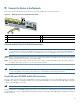
Step 7 Switch the circuit breaker to the ON position.
Step 8 Press the power switch to turn on the router.
Note After powering off the router, wait a minimum of 30 seconds before powering it on again.
Observe the System Startup and Perform a Basic Configuration
Check conditions prior to system startup:
Step 1 Check that all hardware parts and cables are securely attached to the chassis.
Step 2 Check that port adapter configuration information is available, if needed.
Step 3 Check that a CompactFlash Disk is installed.
Step 4 Check that the console terminal is turned on.
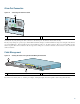
Start the Router
Caution The DC return connection to this system is to remain isolated from the system frame and chassis (DC-I).
Step 1 Place the power switch in the ON (|) position.
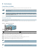
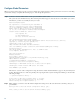
Step 2 Listen for the fans; they should be operating as soon as power is turned on. The following table provides information
about the LEDs as the system starts.
Figure 18 Identifying LEDs and LED Status
No. LED Label LED Color Status
LED flashes when
there is traffic
1 LINK (0/0) LINK (0/0) Green — Yes
2 RJ-45 EN (0/0) RJ-45 enable (0/0) Green In the Power Up state,
the LED is On
No, remains
constantly on
3 LINK (0/1) LINK (0/1) Green — Yes
4 RJ-45 EN (0/1) RJ-45 enable (0/1) Green In the Power Up state,
the LED is On
No, remains
constantly on
5 LINK (0/2) LINK(0/2) Green — Yes
80266
A
LA
R
M
R
J45 E
N
LIN
K
TX
R
X
G
BIC
G
IG
A
B
IT E
T
H
E
R
N
ET 0/2
R
J45 E
N
LIN
K
TX R
X
G
B
IC
G
IG
A
BIT ETH
ER
N
E
T 0/0
R
J45 EN
LIN
K
TX R
X
G
BIC
G
IG
A
B
IT ETH
ER
N
E
T 0/1
CISCO 7301
C
O
N
S
O
LE
A
U
X
C
O
M
P
AC
T
F
LAS
H
S
TA
TU
S
100-240V
, 2A
, 50/60 H
z
24V
=
9A
, 48 - 60V
=
5A
BA
1
2
3
4
5
6
7