Catalyst 4500-X AC-Input Power Supply Installation Note Revised: October 15, 2012 Product Numbers: C4KX-PWR-750AC-F(=) C4KX-PWR-750AC-R(=) C4KX-PWR-BLANK(=) This document covers installing and removing the AC-input power supply in the Catalyst 4500-X series switch chassis. Note AC-input power supplies are not included as part of the basic chassis configuration product numbers. The AC-input power supplies are ordered separately.
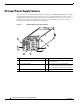
AC-Input Power Supply Features AC-Input Power Supply Features There are two versions of the 750 W AC-input power supply, the C4KX-PWR-750AC-F power supply which has back-to-front airflow (the release lever is color-coded blue indicating cool side) and the C4KX-PWR-750AC-R power supply which has front-to-back airflow (the release lever is color-coded burgundy indicating warm side). Both power supplies provide 750 W of power. Figure 1 shows the AC-input power supply and identifies the major features.
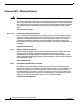
Safety The AC power supply has two LEDS mounted on the lower left corner of the power supply front panel. (See Figure 1.) Together, the two LEDs provide the status of the power supply. Table 1 lists the meanings of the LEDs. Table 1 Note AC-Input Power Supply Status LEDs Meanings OK LED (Green) FAIL LED (Amber) Description Off Off No source AC power is detected by the power supply. Off On Power supply failure (can include overvoltage, overcurrent, overtemperature, or fan failure).
Safety Statement 1071—Warning Definition Warning IMPORTANT SAFETY INSTRUCTIONS This warning symbol means danger. You are in a situation that could cause bodily injury. Before you work on any equipment, be aware of the hazards involved with electrical circuitry and be familiar with standard practices for preventing accidents. Use the statement number provided at the end of each warning to locate its translation in the translated safety warnings that accompanied this device.
Safety Warnung WICHTIGE SICHERHEITSHINWEISE Dieses Warnsymbol bedeutet Gefahr. Sie befinden sich in einer Situation, die zu Verletzungen führen kann. Machen Sie sich vor der Arbeit mit Geräten mit den Gefahren elektrischer Schaltungen und den üblichen Verfahren zur Vorbeugung vor Unfällen vertraut. Suchen Sie mit der am Ende jeder Warnung angegebenen Anweisungsnummer nach der jeweiligen Übersetzung in den übersetzten Sicherheitshinweisen, die zusammen mit diesem Gerät ausgeliefert wurden.
Safety Varning! VIKTIGA SÄKERHETSANVISNINGAR Denna varningssignal signalerar fara. Du befinner dig i en situation som kan leda till personskada. Innan du utför arbete på någon utrustning måste du vara medveten om farorna med elkretsar och känna till vanliga förfaranden för att förebygga olyckor. Använd det nummer som finns i slutet av varje varning för att hitta dess översättning i de översatta säkerhetsvarningar som medföljer denna anordning.
Safety Aviso INSTRUÇÕES IMPORTANTES DE SEGURANÇA Este símbolo de aviso significa perigo. Você se encontra em uma situação em que há risco de lesões corporais. Antes de trabalhar com qualquer equipamento, esteja ciente dos riscos que envolvem os circuitos elétricos e familiarize-se com as práticas padrão de prevenção de acidentes. Use o número da declaração fornecido ao final de cada aviso para localizar sua tradução nos avisos de segurança traduzidos que acompanham o dispositivo.
Safety Catalyst 4500-X AC-Input Power Supply Installation Note 8 OL-26535-01
Tools Required Tools Required No specific tools are required to install or remove the AC-input power supply. Installing the Power Supply To install the AC-input power supply, follow these steps: Step 1 Remove the power supply from the shipping packaging and discard the packaging. Step 2 Verify that the new power supply has the correct airflow direction (front-to-back or back-to-front) for your situation.
Installing the Power Supply Note Step 3 The chassis determines which airflow direction is correct by polling all of the fan assemblies and the power supplies. The airflow direction for all of the devices must be the same. If the airflow direction of the replacement power supply or the redundant power supply does not match the fan assemblies airflow direction, the system software shuts down the power supply and generates a power supply mismatch error message on the console.
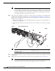
Removing the Power Supply Installing the AC-Input Power Supply 332208 Figure 3 Step 6 Verify that you have the correct source AC power cord for your installation. See the “Power Cords” section on page 14 for a list, including descriptions and illustrations, of the AC power cords supported on the power supply. Step 7 Attach the AC power cord’s appliance connector to the AC-in receptacle on the power supply and secure the power cord in place with the velcro retaining strap on the power supply.
Removing the Power Supply Step 3 Grasp the power supply handle with your forefinger and place your thumb on the power supply release handle. Step 4 Squeeze your forefinger and thumb together and pull on the power supply handle to release the power supply from the chassis bay. (See Figure 4.) Removing the AC-Input Power Supply 332209 Figure 4 Step 5 Slide the power supply out of the chassis bay. Note The power supply is approximately 14 inches (35.56 cm) long.
Power Supply Specifications Power Supply Specifications Table 2 lists and describes the electrical specifications for the 750 W AC-input power supply.
Power Cords Table 3 lists the physical specifications of an AC-input power supply (C4KX-PWR-750AC-R= or C4KX-PWR-750AC-F=). Table 3 Dimensions and Weight for an AC-Input Power Supply Specification Description AC-input power supply dimensions (H x W x D) 1.57 x 2.15 x 14.28 in (3.99 x 5.46 x 36.27 cm) Weight 2 lb (0.91 kg) Shipping box dimensions, spare power supply (H x W x D) 4.38 x 7.13 x 20.13 in (11.13 x 18.11 x 51.13 cm) Shipping weight 3.7 lb (1.
Power Cords Figure 5 CAB-9K10A-SW=, CAB-C15-ACS= (AC Power Cord, Switzerland) Connector: IEC 60320 C15 186578 Plug: MP232-R Cordset rating: 10 A, 250 V Length: 8 ft. 2 in (2.5 m) Figure 6 CAB-AS3112-C15-AU= (AC Power Cord, Australia) Cordset rating: 10 A, 250 V Length: 8 ft 2 in. (2.
Power Cords Figure 8 CAB-BS546-C15-SA= (AC Power Cord, South Africa, India) Cordset rating 10A, 250V 6 ft. 0 in (1.83 m) Plug: BS 546 (SABS 164-1) 196271 Connector: IEC 60320 C15 Figure 9 CAB-C2316-C15-IT= (AC Power Cord, Italy) Plug: CEI 23-16/7 Cordset rating: 10 A, 250 V Length: 8 ft 2 in. (2.5 m) 113349 Connector: IEC 60320 C15 Figure 10 CAB-CEE77-C15-EU= (AC Power Cord, Europe) 113348 Plug: CEE 7/7 Cordset rating: 16 A, 250 V Length: 8 ft 2 in. (2.
Power Cords Figure 11 CAB-IR2073-C15-AR= (AC Power Cord, Argentina) Plug: IRAM 2073 Cordset rating: 10 A, 250 V Length: 8 ft 2 in. (2.5 m) 113346 Connector: IEC 60320 C15 Figure 12 CAB-US515-C15-US= (AC Power Cord, North America) Connector: IEC60320/C15 Plug: NEMA 5-15P Figure 13 192260 Cordset rating 13A, 125V (8.2 feet) (2.5m) CAB-C15-ISR= (AC Power Cord, Israel) Cordset rating: 10 A, 250 V Length: 8 ft 2 in. (2.
Power Cords Figure 14 CAB-C15-JPN= (AC Power Cord, Japan) Cordset rating:12 A, 125 V Length: 8 ft 2 in. (2.5 m) Connector: IEC 60320 C15 334127 Plug: JIS C8303 Figure 15 CAB-EL223-C15-BR= (AC Power Cord, Brazil) Connector: IEC 60320 C15 334128 Plug: EL223 Cordset rating: 10 A, 250 V Length: 8 ft 2 in. (2.
Related Documentation Related Documentation Table 5 lists the documentation supporting the Catalyst 4500-X series switch that is available at http://www.cisco.com/ Table 5 Documentation Supporting the Catalyst 4500-X Series Switch Title Description of Contents Catalyst 4500-X Series Switch Installation Note Contains instructions for rack-mounting the switch chassis.
Obtaining Documentation and Submitting a Service Request Obtaining Documentation and Submitting a Service Request For information on obtaining documentation, submitting a service request, and gathering additional information, see the monthly What’s New in Cisco Product Documentation, which also lists all new and revised Cisco technical documentation, at: http://www.cisco.com/en/US/docs/general/whatsnew/whatsnew.