C H A P T E R 3 Initial Configuration This chapter describes how to configure the Cisco ONS 15530 so it can be accessed by other devices.
Chapter 3 Initial Configuration Starting Up the Cisco ONS 15530 The CPU switch module provides a slot on the front panel that accommodates a CompactFlash card. You can use the CompactFlash card for system image upgrades, FPGA image upgrades, statistics gathering, and other file system applications. The Cisco ONS 15530 supports redundant operation with dual CPU switch modules. The CPU switch modules reside in slots 5 and 6, the sixth and seventh slots from the left as you face the chassis.
Chapter 3 Initial Configuration About Passwords Modem Support The auxiliary port of the Cisco ONS 15530 provides modem connection support. The following settings on the modem are required: • Enable auto answer mode. • Suppress result codes. • Ensure auxiliary port terminal characteristics, such as speed, stop bits, and parity, match those of the modem. You can configure your modem by setting the DIP switches on the modem itself or by setting them through terminal equipment connected to the modem.
Chapter 3 Initial Configuration Configuring IP Access on the NME Interface Configuring IP Access on the NME Interface The Fast Ethernet interface, or NME, on the active CPU switch module, named fastethernet 0, is the management interface that allows multiple, simultaneous Telnet or SNMP network management sessions. You can remotely configure the Cisco ONS 15530 through the Fast Ethernet interface, but first you must configure an IP address so that the active CPU switch module is reachable.
Chapter 3 Initial Configuration Configuring IP Access on the NME Interface Command Purpose Step 10 Switch(config-if)# duplex {auto | full | half} Specifies the duplex mode. The default is auto (autonegotiation). Step 11 Switch(config-if)# no shutdown Enables the interface. Step 12 Switch(config-if)# exit Returns to global configuration mode. Switch(config)# Step 13 Switch(config)# line vty line-number Switch(config-line)# Enters line configuration mode for virtual terminal connections.
Chapter 3 Initial Configuration Configuring the Host Name Example Switch# show interfaces fastethernet 0 FastEthernet0 is up, line protocol is up Hardware is AmdFE, address is 0000.1644.28ea (bia 0000.1644.28ea) Internet address is 172.20.54.
Chapter 3 Initial Configuration About NTP Step 3 Command Purpose name(config)# end Returns to privileged EXEC mode. The prompt indicates that the host name has been set to the new name. name# Step 4 name# copy system:running-config nvram:startup-config Note The host name is also synchronized with the standby CPU switch module. The host name prompt on the standby CPU switch module appears with “sby-” as a prefix. Saves your configuration changes to NVRAM.
Chapter 3 Initial Configuration Configuring NTP implementation allows a machine to be configured so that it acts as though it is synchronized using NTP, when in fact it has determined the time using other means. Other machines then synchronize to that machine using NTP. A number of manufacturers include NTP software for their host systems, and a version for systems running UNIX and its various derivatives is also publicly available. This software allows host systems to be time-synchronized as well.
Chapter 3 Initial Configuration Configuring Security Features Configuring Security Features The Cisco ONS 15530 supports the following Cisco IOS software security features: • AAA (authentication, authorization, and accounting) • Kerberos • RADIUS • TACACS+ • Traffic filters and firewalls • Passwords and privileges Configuring AAA This section describes the AAA features supported by the Cisco ONS 15530.
Chapter 3 Initial Configuration Configuring Security Features method you have implemented) in the form of accounting records. Each accounting record contains accounting attribute-value (AV) pairs and is stored on the security server. This data can then be analyzed for network management, client billing, and auditing. Refer to the “Configuring Accounting” chapter in the Cisco IOS Security Configuration Guide.
Chapter 3 Initial Configuration Configuring Security Features Configuring TACACS+ To configure your router to support TACACS+, perform the following tasks: Step 1 Use the aaa new-model global configuration command to enable AAA. AAA must be configured if you plan to use TACACS+. Refer to the “AAA Overview” chapter in the Cisco IOS Security Configuration Guide. Step 2 Use the tacacs-server host command to specify the IP address of one or more TACACS+ daemons.
Chapter 3 Initial Configuration About CPU Switch Module Redundancy Refer to the “Configuring Passwords and Privileges” part in the Cisco IOS Security Configuration Guide. About CPU Switch Module Redundancy The Cisco ONS 15530 supports fault tolerance by allowing the standby CPU switch module to take over if the active CPU switch module fails. This standby, or redundant, CPU switch module runs in hot-standby state.
Chapter 3 Initial Configuration About CPU Switch Module Redundancy Table 3-1 CPU Switch Module Hardware States State Description Active Processor card is currently providing clock signals and control for all system cards. The active CPU switch module responds to the configured management IP address. Standby Processor card is partially booted in hot-standby state waiting to switch over when the active CPU switch module fails, when it is rebooted or removed, or when a manual switchover is requested.
Chapter 3 Initial Configuration About CPU Switch Module Redundancy Table 3-2 CPU Switch Module Software States State Description Disabled The standby CPU switch module is not yet running the system image or is in maintenance mode. Standby cold The standby CPU switch module is running the system image but has not begun to synchronize data from the active CPU switch module.
Chapter 3 Initial Configuration Configuring CPU Switch Module Redundancy • The active CPU switch module fails. The standby CPU switch module takes over as the active CPU switch module, using the last synchronized running configuration file (or the last saved startup configuration file if the running configuration file synchronization was disabled or failed). • A switchover is manually forced with the redundancy switch-activity command.
Chapter 3 Initial Configuration Configuring CPU Switch Module Redundancy Forcing a Switchover from ROM Monitor Mode You can manually force the standby CPU switch module to take over as the active CPU switch module ROM monitor mode. To force a switchover from ROM monitor mode, enter the following commands on the active CPU switch module CLI: Note Command Purpose switchover Causes a CPU switch module reset and switchover. The CPU switch module stays in ROM monitor mode.
Chapter 3 Initial Configuration Configuring CPU Switch Module Redundancy Configuring Autoboot If you have changed the default configuration register value from autoboot, you can change it back by performing the following steps, beginning in global configuration mode: Command Purpose Step 1 Switch(config)# config-register 0x2102 Sets the configuration register for autoboot.1 Step 2 Switch(config)# boot system bootflash:filename Sets the BOOT environment variable.
Chapter 3 Initial Configuration Configuring CPU Switch Module Redundancy Example The following example shows the contents of the configuration register: Switch# show version Cisco Internetwork Operating System Software IOS (tm) ONS-15530 Software (manopt-M0-M), Experimental Version 12.1(20010221:0] Copyright (c) 1986-2001 by cisco Systems, Inc. Compiled Tue 20-Feb-01 18:40 by lthanvan Image text-base: 0x60010968, data-base: 0x604D8000 ROM: System Bootstrap, Version 12.
Chapter 3 Initial Configuration Configuring CPU Switch Module Redundancy Example The following example shows how to manually synchronize the running configuration: Switch# redundancy manual-sync running-config Enabling and Disabling Automatic Synchronization You can enable and disable automatic synchronization of the running configuration and the startup configuration between the two CPU switch modules.
Chapter 3 Initial Configuration Configuring CPU Switch Module Redundancy Configuring Maintenance Mode You can configure the Cisco ONS 15530 to enter the redundancy maintenance mode. Configuration synchronizations and standby CPU switch module fault reporting are suppressed in maintenance mode. Upon exiting maintenance mode and reverting to redundant mode, the standby switch CPU switch module reboots to the hot-standby state.
Chapter 3 Initial Configuration Configuring CPU Switch Module Redundancy Examples The following example shows the CPU switch module redundancy configuration and status: Switch# show redundancy summary Redundant system information ---------------------------Available Uptime: Time since last switchover: Switchover Count: 3 days, 4 hours, 35 minutes 10 hours, 30 minutes 1 Inter-CPU Communication State:UP Last Restart Reason: Switch over Software state at switchover: ACTIVE Last Running Config Running Conf
Chapter 3 Initial Configuration Configuring CPU Switch Module Redundancy The following example shows the CPU switch module capabilities: Switch# show redundancy capability CPU capability support Active CPU Sby CPU Sby Compat ---------- ---------- ----------48 MB 48 MB OK 16 MB 16 MB OK 512 KB 512 KB OK 16 MB 16 MB OK 4.6 4.6 OK 1.43 1.43 OK CPU capability description ---------------------------------------CPU DRAM size CPU PMEM size CPU NVRAM size CPU Bootflash size CPU hardware major.
Chapter 3 Initial Configuration Configuring CPU Switch Module Redundancy deviation_numbers_str manufacturing_use rma_number_str rma_failure_code_str oem_str clei_str snmp_oid_substr schematic_num_str Backplane IDPROM field --------------------------hardware_major_version hardware_minor_version engineering_use_str crc16 user_track_string YES YES YES YES YES YES YES YES Match ----YES YES YES OK NO N/A 0 N/A 0 Cisco TBD TBD 92-4568-03 Local CPU -------------------3 1 LAB Prototype 52960 hello PhyAlias te
Chapter 3 Initial Configuration Configuring CPU Switch Module Redundancy Configuring Privileged EXEC Mode Access on the Standby CPU Switch Module Access to privileged EXEC mode from the standby CPU switch module CLI can be enabled from the active CPU switch module CLI. This feature provides extra security for the Cisco ONS 15530 system.
Chapter 3 Initial Configuration About the Software Configuration Register Example The following example shows the privileged EXEC mode access status on the standby CPU switch module: Switch# show redundancy summary Redundant system information ---------------------------Available Uptime: 15 hours, 27 minutes sysUpTime (switchover clears): 15 hours, 27 minutes Switchover Count: 0 Inter-CPU Communication State: DOWN Last Restart Reason: Normal boot Last Running Config Running Config sync Last Startup Conf
Chapter 3 Initial Configuration About the Software Configuration Register • Enable booting from a TFTP server • Recover a lost password • Boot the system manually using the boot command at the bootstrap program prompt.
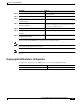
Chapter 3 Initial Configuration About the Software Configuration Register Table 3-5 Register Settings for Broadcast Address Bit 14 Bit 10 Address () 0 0 0 1 1 0 1 1 Bit 12 and bit 11 in the configuration register determine the data transmission rate of the console terminal. Table 3-6 shows the bit settings for the four available rates. The factory-set default data transmission rate is 9600.
Chapter 3 Initial Configuration About the Software Configuration Register Table 3-7 describes the values for the boot field. Table 3-7 Configuration Register Boot Field Values Boot Field Value Description 0x0 (0-0-0-0) Stays at the system bootstrap prompt. You must boot the operating system manually by giving a boot command to the ROMMON system bootstrap environment. 0x1 (0-0-0-1) Boots the first system image in onboard Flash SIMM.
Chapter 3 Initial Configuration Changing the Software Configuration Register Changing the Software Configuration Register To change the configuration register, perform the following steps: Step 1 Command Purpose Switch# configure terminal Enters global configuration mode. Switch(config)# Step 2 Switch(config)# config-register value Sets the contents of the configuration register. The value is a hexadecimal number preceded by 0x. See Table 3-4 for the list of values.
Chapter 3 Initial Configuration About Fan Failure Shutdown About Fan Failure Shutdown The Cisco ONS 15530 fan assembly is located at the bottom of the chassis and contains six individual fans and a fan controller board. The controller board monitors the status of each fan and reports the status to the CPU switch modules. If a single fan fails, a minor alarm is reported to the CPU switch module. However, the chassis will never reach a critical high temperature when only one fan fails.
Chapter 3 Initial Configuration Configuring Fan Failure Shutdown Displaying the Fan Tray Failure Shutdown Configuration To display the fan tray failure shutdown configuration, use the following EXEC command: Command Purpose show environment Displays the fan tray failure shutdown configuration.
Chapter 3 Initial Configuration Configuring Fan Failure Shutdown Cisco ONS 15530 Configuration Guide and Command Reference 3-32 78-16019-02, Cisco IOS Release 12.