Cisco Aironet 1600/2600/3600 Series Access Point Deployment Guide ABSTRACT: This document covers the theory of operation and installation for Cisco 2600 and 3600 Series Access Points (APs), as part of a Cisco wireless LAN (WLAN) solution.
Cisco Aironet Access Point Deployment Guide Revision History Document Number: EDCS‐1188900 (replaces EDCS‐1130881) Document Author: Frederick Niehaus (fredn) Author's Organization: WNG (WNBU) TME Document Date / Version: 12/12/12 version 3.0 Cisco Systems Copyright © 2012 Cisco Systems, Inc. All rights reserved.
Cisco Aironet Access Point Deployment Guide Table of Contents Revision History....................................................................................................................... 2 Table of Contents .................................................................................................................... 3 Cisco Aironet Series Access Points ........................................................................................... 4 Internal and External Antennas ..............
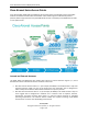
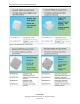
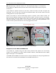
Cisco Aironet Access Point Deployment Guide Cisco Aironet Series Access Points Cisco Aironet 3600, 2600, 1600, and 600 Series Access Points (APs) provide highly secure and reliable wireless connections for both indoor and outdoor environments. Figure 1 illustrates the product portfolio, which ranges from the entry‐level 600 Series for basic connectivity to the 3600 Series for best‐ in‐class performance.
Cisco Aironet Access Point Deployment Guide Figure 2: AP 3600 Models and Eco‐Packs Figure 3: AP 2600 Models and Eco‐Packs Cisco Systems Copyright © 2012 Cisco Systems, Inc. All rights reserved.
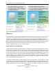
Cisco Aironet Access Point Deployment Guide Figure 4: AP 1600 Models and Eco‐Packs 3600 Series The Cisco 3600 Series Access Point (AP 3600) targets customers who require support for mission‐critical applications. The AP 3600 embodies ClientLink 2.0, an innovative antenna technology comprising four transmit radios and four receive radios called 4X4 Multiple Input Multiple Output (MIMO) and three spatial stream (3SS) beamforming, together referenced as 4x4:3. ClientLink 2.
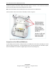
Cisco Aironet Access Point Deployment Guide module may require a local power supply, Cisco power injector, .3at PoE+, or use of the Cisco Enhanced PoE because the module may draw power greater than 15.4W. Note: Cisco Enhanced PoE was created by Cisco and is the forerunner to 802.3at PoE+. Feature modules slide into the bottom of AP 3600, as shown in Figure 5.
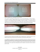
Cisco Aironet Access Point Deployment Guide Figure 6: LED Appearance in the AP 3600i and the AP 3500 From a side view, the AP 3600i is slightly thicker (2.11”) than the AP 3500 (1.84”), as shown in Figure 7. The thicker size allows for additional radio support and printed circuit board area, as well as feature modules for future capabilities.
Cisco Aironet Access Point Deployment Guide Note: Beamforming to a 3SS client requires n+1 radio frequency (RF) design. To accomplish this, the AP 3600 has an additional radio per band, which improves client performance by using Cisco ClientLink 2.0. The AP 3500e has separate antennas for each band, 2.4 GHz and 5 GHz, and does not support 3SS technology, since it has only two transceivers (transmitter/receiver) and one extra receiver per band enabling operation up to two spatial streams.
Cisco Aironet Access Point Deployment Guide Figure 9: Front View of the AP2600 and the AP 3600 The AP 2600 is a 3X4:3SS, so ClientLink does not beamform to 3SS clients; however, it does beamform at legacy, one, and two spatial stream rates. The AP 3600 is a 4X4:3SS, supporting an extra transmitter chain for additional downlink performance for all bands and clients. The AP 3600 has slightly higher performance and beamforms to legacy, one, two, and three spatial stream rates and .
Cisco Aironet Access Point Deployment Guide Figure 10: Back View of the AP 2600 Because of these similarities, there is no need to repeat a site survey for the AP 2600 if a survey exists for the AP 3600. Introduction to the 1600 Series The Cisco Aironet 1600 Series Access Point (AP1600), shown in Figure 11, is a second generation, entry‐ level AP. Figure 11: AP 1600 Key Features Significant features include: ClientLink 2.
Cisco Aironet Access Point Deployment Guide Figure 12: Comparison of CleanAir Features in the 1600/2600/3600 Series Comparison of Indoor Access Points A comparison of the indoor access points for the 3600/2600/1600/600 Series is shown in Figure 13. Figure 13: Comparison of the 3600/2600/1600/600 Series Cisco Systems Copyright © 2012 Cisco Systems, Inc. All rights reserved.
Cisco Aironet Access Point Deployment Guide Hardware and Mounting Options The AP 1600, 2600, and 3600 have the same mounting options and share similar dimensions, as shown in Figure 14. There are slight cosmetic differences; for example, there are three antennas on the AP 1600. Figure 14: Mechanical Drawing of the AP 2600 and the AP 3600 Brackets and Clips There are many different installation options available depending upon the requirements of the customer.
Cisco Aironet Access Point Deployment Guide Figure 15: Access Point Bracket Choices If the AP needs to be mounted directly to a ceiling on the gridwork, AIR‐AP‐BRACKET‐1 mounts flush and has the lowest profile. Since some ceiling tiles are recessed, two different styles of ceiling clips, recessed and flush rails, are available to mount the bracket to the ceiling gridwork. (See Figure 16).
Cisco Aironet Access Point Deployment Guide Figure 17: Channel Rails Figure 18: AIR‐CHNL‐ADAPTER (left); Channel Rails (right) Figure 19: AIR‐CHNL‐ADAPTER and Ceiling Grid Clip (left); Finished Installation (right) Installation in Ceiling Tiles Many hospitals and other carpeted enterprise environments prefer a more streamlined look and wish to install the AP directly into the tile. In this case, use the optional Cisco AIR‐AP‐BRACKET‐3, as shown in Figure 20.
Cisco Aironet Access Point Deployment Guide Figure 20: Optional AIR‐AP‐BRACKET‐3 for Installation of APs into Ceiling Tiles Use the “beauty ring” as a template to cut the tile. Cisco does not offer custom cut tiles but the tiles are easy to cut with a carpet knife or electric tool such as the Dremel™ or Rotozip™ rotary cutting tool. A metal rail that extends the length of the tile supports the AP above the ceiling if the tile becomes wet or otherwise fails.
Cisco Aironet Access Point Deployment Guide Instead of wall‐mounting APs with internal antennas, you can: Use the AP 3600e with dipoles or patch antennas. Use an optional wall mount bracket, such as the Oberon P/N 1029‐00, that puts the AP 3600i or the AP 3500e into a horizontal orientation. (See Figure 21.) Use this Oberon bracket unless you have a hotspot, kiosk, or small venue scenario and roaming is not an issue.
Cisco Aironet Access Point Deployment Guide Figure 22: Oberon Skin Unique Installations Clean Rooms Many hospitals and factories have requirements to wipe down or gently spray the environment with a chemical (often diluted material that has cleaning and disinfectant properties). The AP 3600 is ideal for these types of applications because it is designed with a purpose guild Wi‐Fi chipset with enterprise and industrial class components.
Cisco Aironet Access Point Deployment Guide Figure 24: Oberon Metal Enclosure Above Ceiling Tiles The AP 2600 and the AP 3600 are rated for installation in the Plenum area (UL‐243). Many customers prefer to install the AP above a drop ceiling for aesthetic reasons, so that nothing is visible on the ceiling. This type of installation may also be appropriate in high theft areas such as classrooms or areas where policy dictates that nothing can be visible on the ceiling.
Cisco Aironet Access Point Deployment Guide Figure 25: Installation of an AP Above Ceiling Tiles Note: Install APs above the ceiling tiles only when mounting below the ceiling is not an option. “Above ceiling tiles” installations can certainly degrade advanced RF features such as voice and location, so verify coverage and performance and ensure the tiles are not conductive. Mount the AP as close to the inside middle of the tile as possible, and avoid areas with obstructions and clutter. (See Figure 26.
Cisco Aironet Access Point Deployment Guide Note: Some APs may not be certified for outdoor deployments in a NEMA enclosure. For example, in some areas of the world, regulatory agencies may permit AP outdoor NEMA enclosures if the AP is indoors (such as a freezer or garden area) but may prohibit use of those NEMA enclosures outdoors. This seems to vary with weather radar compliance, UNII‐1 compliance, and so forth.
Cisco Aironet Access Point Deployment Guide Figure 28: Metal Pins or Padlocks for Areas of High Vibration Warehouse and Factory Warehouse installations are often difficult because of the very high ceilings and the clutter of the material in storage. As part of your site survey, always check the coverage when the warehouse is fully stocked, since the material in storage can change the RF coverage and interfere with uniform coverage.
Cisco Aironet Access Point Deployment Guide Figure 29: AP Placement in Warehouse To mount an AP at the end of a pipe or electrical conduit box, use the universal bracket Cisco AIR‐AP‐ BRACKET‐2, because it mates to the holes of most electrical boxes. (See Figure 30.) Conduit and adapters are available at most electrical or home repair centers. Cisco Systems Copyright © 2012 Cisco Systems, Inc. All rights reserved.
Cisco Aironet Access Point Deployment Guide Figure 30: Installation of an AP onto an Electrical Conduit Box Ethernet Cable Recommendation While the AP 1600/2600 and the AP 3600 work well with CAT‐5e for new cable installations, Cisco recommends that customers use CAT6a because CAT6a cable is required by the 10GE standard. Antenna Cable Recommendation Keep antenna cable runs as short as possible.
Cisco Aironet Access Point Deployment Guide Cisco cables carry the part number AIR‐CAB (Aironet Cable) and then a length. For example, a 20’ length of LL cable with RP‐TNC connector is Cisco AIR‐CAB‐020LL‐R. These heavy black cables are not Plenum rated and are primarily for use outdoors or in manufacturing areas.
Cisco Aironet Access Point Deployment Guide Common or Distributed Antenna System (DAS) Due to the dual‐band nature of the antenna system on the AP 2600 and the AP 3600, along with key features such as ClientLink 2.0 beamforming, the AP 2600 and the AP 3600 are not recommended for deployments on Distributed Antenna Systems (DAS). Note: Cisco does not certify, endorse or provide RF support for Wi‐Fi deployments over any DAS.
Cisco Aironet Access Point Deployment Guide External Antenna Options and Patterns AP 1600/2600 and AP 3600e The following dual‐band, dual‐resonant antennas are available for use with the AP 1600e*/2600e and the AP 3600e: AIR‐ANT2524DB‐R AIR‐ANT2524DW‐R AIR‐ANT2524DG‐R AIR‐ANT2524V4C‐R AIR‐ANT2544V4M‐R AIR‐ANT2566P4W‐R – – – – – – Dual‐band (Black) dipole Dual‐band (White) dipole Dual‐band (Grey) dipole Dual‐band Omni‐directional Dual‐band Omni‐directional Dual band directional (4 required) (4 required)
Cisco Aironet Access Point Deployment Guide Figure 32: Specifications for the AIR‐ANT2524Dx‐R Dual‐Band Dipole Antenna Figure 33: Radiation Pattern for the AIR‐ANT2524Dx‐R Dual‐Band Dipole Antenna Cisco Systems Copyright © 2012 Cisco Systems, Inc. All rights reserved.
Cisco Aironet Access Point Deployment Guide Figure 34: Specifications for the AIR‐ANT2566P4W‐R Dual‐Band Patch Antenna Figure 35: Radiation Pattern for the AIR‐ANT2566P4W‐R Dual‐Band Patch Antenna If the antenna is mounted on a wall, the azimuth (in red) is the signal going forward from the antenna, and the elevation (in blue) is the up/down pattern. Cisco Systems Copyright © 2012 Cisco Systems, Inc. All rights reserved.
Cisco Aironet Access Point Deployment Guide Figure 36: Specifications for the AIR‐ANT2524V4C‐R Dual‐Band Omni Antenna Figure 37: Radiation Pattern for the AIR‐ANT2524V4C‐R Dual‐Band Omni Antenna Cisco Systems Copyright © 2012 Cisco Systems, Inc. All rights reserved.
Cisco Aironet Access Point Deployment Guide Antenna type 4-element MIMO omnidirectional Operating frequency range 2400-2484 MHz Nominal input impedance 50 VSWR 2:1 or less Peak gain 2.4-GHz band: 4 dBi 5150-5850 MHz 5-GHz band: 4 dBi Polarization Linear, vertical Azimuth plane (3 dB beamwidth) Ominidirectional Elevation plane (3 dB beamwidth 2.4-GHz band: 60° Length 8.6 in (21.8 cm) Diameter 6.3 in (16 cm) Weight Antenna: 1.48 lb. (671.5 g); Cable 3-ft. (91.
Cisco Aironet Access Point Deployment Guide AP 3600i, AP 2600i, and AP 1600i Figures 40 and 41 show the radiation patterns for the AP 3600i (internal antenna model). Figures 42 and 43 show the radiation patterns for the AP 2600i (internal antenna model). Figures 44 and 45 show the radiation patterns for the AP 1600i (internal antenna model). Figure 40: Radiation Patterns for the AP 3600i @ 2.4 GHz Figure 41: Radiation Patterns for the AP 3600i @ 5 GHz Cisco Systems Copyright © 2012 Cisco Systems, Inc.
Cisco Aironet Access Point Deployment Guide Figure 42: Radiation Patterns for the AP 2600i @ 2.4 GHz Figure 43: Radiation Patterns for the AP 2600i @ 5 GHz Cisco Systems Copyright © 2012 Cisco Systems, Inc. All rights reserved.
Cisco Aironet Access Point Deployment Guide Figure 44: Radiation Patterns for the AP 1600i @ 2.4 GHz Figure 45: Radiation Patterns for the AP 1600i @ 5 GHz Cisco Systems Copyright © 2012 Cisco Systems, Inc. All rights reserved.
Cisco Aironet Access Point Deployment Guide External Antenna Deployments All Cisco antenna connectors are labeled A, B, C, and so on. A has a higher priority than B, C, or D; therefore, if the access point supports say three or four antennas and you only have two antennas, use ports A and B until you could install the additional antennas. It is possible to support 802.11a/b/g clients or single spatial stream N clients with only one or two antennas.
Cisco Aironet Access Point Deployment Guide Figure 47: Port Spacing on the AP 1600 The best antenna placement is the one where the antenna is physically closest to the actual users. If you are mounting multiple, single package, dual‐band antennas externally, such as dipoles, spacing is not critical. Try to space the antennas as far apart as practical (with A and B the furthest apart), but no further than 10’ apart, since antennas should be in same RF coverage area. (See Figure 48.
Cisco Aironet Access Point Deployment Guide Note: Avoid using single‐band (single‐radiating element antennas) like those used with the earlier AP 3500, because they are not fully compatible with the newer AP 1600/2600 and AP 3600. Antennas for the AP 1260 and the AP 3500 are single‐radiating element antennas made for each individual band. The AP 3600, 2600, and 1600 use dual‐band, dual‐radiating element antennas and are branded with an orange marking. (See Figures 46 and 47.) When using 802.
Cisco Aironet Access Point Deployment Guide Figure 50: High Gain Antenna (AIR‐ANT2480V‐N) with Cover Removed 802.11n, Spatial Streams, and Beamforming For a video on the fundamentals of spatial streams, see the following URL: http://www.cisco.com/en/US/netsol/ns767/index.html MIMO, which refers to a radio system that has multiple separate receive and transmit paths, is at the heart of 802.11n. MIMO systems are described by the number of transmitters and receivers in the system.
Cisco Aironet Access Point Deployment Guide Figure 51: AP 3500i/e — 2x3:2 System (Two Transmitters, Three Receivers, Supporting Two Spatial Streams) Spatial streams, the act of transmitting information out of more than one antenna port concurrently, requires that the AP have at least two or more transmitters and support elements of 802.11n (for example, support of multiple spatial streams). With 802.11a/b/g, data rates were actual Mbps rates like 2, 11, and 54 Mbps and were done with one transmitter.
Cisco Aironet Access Point Deployment Guide Figure 52: MCS: Two Spatial Stream Bonded Channel Supports up to 300 Mbps Unlike the AP 3500, the newer AP 3600 supports 3SS with twice as many transmitters (four per band), which enables faster data rates of up to 450 Mbps. There is an extra radio for redundancy and enhanced performance both upstream and downstream. The AP 3600 can also beamform to 3SS clients.
Cisco Aironet Access Point Deployment Guide The AP 2600, while similar to the AP 3600, is slightly different since it is a 3x4:3. This means that the AP 2600 also has four antennas to help on the receive (upstream signal) but uses only three transmitters on the downstream side. The yellow sections of the MCS chart (see Figure 54) depict the faster data rates supported by the AP 3600. The AP 3600 supports 802.11a/b/g rates as well as 802.11n rates of MCS values 0‐23.
Cisco Aironet Access Point Deployment Guide the Intel card or open a case with Intel or the laptop manufacturer for a possible remedy. During the AP 3600 beta trials, Cisco observed differences in performance with different notebooks using the Intel 6300 card. Note: Sometimes it can be difficult to reliably maintain a 3SS link, since it is easy for the client to rate‐shift out of the 3SS mode. The ability to maintain a 3SS link varies with the quality of the client and the test environment.
Cisco Aironet Access Point Deployment Guide Figure 56: Beamforming, Constructive Interference, and Destructive Interference Figure 57 provides a visual comparison of ClientLink 1.0, using one spatial stream, and ClientLink 2.0, using three spatial streams. Unlike the AP 3500, the AP 3600 provides multiple spatial streams using four transceivers for even greater performance. The AP 3600 can beamform to all 802.11a/g and 802.11n one, two, and three spatial stream clients.
Cisco Aironet Access Point Deployment Guide Note: In order to beamform to clients using three spatial streams, since three transmitters are used in the transmissions, the AP needs at least one additional radio to beamform. The AP 3600 has four radios per band and can beamform to clients using three spatial streams. To summarize, ClientLink 2.0 takes the received signals heard from the client on the uplink and calculates how the multipath signal looked from those streams.
Cisco Aironet Access Point Deployment Guide Figure 58: AP 3600 Site Survey Ranges (Typical Cell Sizes Unchanged; AP 3500 and AP 3600 Cell Sizes Unchanged) Figure 59: Site Survey Sensitivity and SNR Note: The SNR for 3SS is 28 dB, per IEEE, but Cisco RF engineers recommend 30‐32 dB for best performance. Cisco Systems Copyright © 2012 Cisco Systems, Inc. All rights reserved.
Cisco Aironet Access Point Deployment Guide Figure 60: Site Survey Sensitivity, RSSI/SNR Guidelines, and SNR General Guidelines Following are general guidelines for all access points. Always try to mount the AP as close to the users as possible for best performance. Be aware of the environment. For example, if hospitals have metal doors, coverage can change when the doors close. Old buildings can have metal grid work hidden under plaster or asbestos.
Cisco Aironet Access Point Deployment Guide Figure 61: Example of Channel Usage in 2.4 and 5 GHz (Two Channels used if 40 MHz) Try to determine which clients will be used and check the coverage using those clients. For example, a PDA or Wi‐Fi phone might not have the same range as a notebook or tablet. Tip: Verify coverage using the worst performing clients that you intend to deploy.
Cisco Aironet Access Point Deployment Guide Examples of Improper Installations It is very difficult to provide good Wi‐Fi service with an improper installation, so use common sense when mounting devices: Keep the AP away from clutter and metal objects. (See Figures 62 and 63.) The AP should be level and secure so that it does not sway or move. (See Figure 64.) Try to locate the AP as close to the users as possible.
Cisco Aironet Access Point Deployment Guide Figure 63: Improper Installation — Antennas Against Metal Figure 64: Improper Installation — AP not Level or Stable Tip: When mounting antennas outside, always mount with the antenna leads and drain holes down so that rainwater does not enter the antenna. This approach is not necessary for indoor mounting. (See Figure 65.) Use Coax‐Seal to protect against weather exposure but do not obstruct the drain holes. (See Figure 66.
Cisco Aironet Access Point Deployment Guide Figure 65: AP Mount with Antenna Leads and Drain Holes Down Figure 66: Sealant Cisco Systems Copyright © 2012 Cisco Systems, Inc. All rights reserved.
Cisco Aironet Access Point Deployment Guide Questions and Answers Q1: Which AP is best for manufacturing and warehouse areas? A1: In general, the AP 2600e or the AP 3600e is the first choice because these external antenna models have the highest operating temperature range ‐20 to 55°C. The AP 1600 can also be used but has a slightly lower operating temperature ‐20 to 50°C. If temperature is not a concern, use an internal antenna model (AP 1600i, 2600i, and 3600i).
Cisco Aironet Access Point Deployment Guide Useful URLs AP 3600 datasheet: http://www.cisco.com/en/US/products/ps11983/index.html AP and controller datasheets: http://www.cisco.com/en/US/products/hw/wireless/index.html Cisco antenna reference guide: www.cisco.com/go/antenna‐ref Why buy Cisco brand antennas: http://www.cisco.com/en/US/prod/collateral/wireless/ps5678/ps10981/white_paper_c11‐671769.pdf Antenna patterns and their meanings: http://www.cisco.