C H A P T E R 5 Parameters and Defaults This section provides information on the parameters and defaults that you can use to create your own Cisco ATA configuration file. This section also includes the voice configuration menu code for each parameter that has such a code. Parameters are divided into categories based on their functionality.
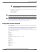
Chapter 5 Parameters and Defaults Configuration Text File Template Note A tool called bitaid.exe is bundled with your Cisco ATA software. You can use this tool to help you configure values of Cisco ATA bitmap parameters. The tool prompts you for the necessary information. – Extended IP address—IP address followed by port number (for example, 192.168.2.170.9001) – IP address (e.g. 192.168.2.
Chapter 5 Parameters and Defaults User Interface (UI) Security Parameter UID0:0 UID1:0 UseLoginID:0 LoginID0:0 LoginID1:0 PWD0:0 PWD1:0 AutMethod:0x00000000 GateWay:0 MediaPort:16384 RxCodec:1 TxCodec:1 LBRCodec:0 AudioMode:0x00150015 NumTxFrames:2 TOS:0x0000A8B8 CallFeatures:0xffffffff PaidFeatures:0xffffffff CallCmd:Af;AH;BS;NA;CS;NA;Df;EB;Ff;EP;Kf;EFh;HH;Jf;AFh;HQ;I*67;gA*82;fA#90v#;OI;H#72v#; bA#74v#;cA#75v#;dA#73;eA*67;gA*82;fA*70;iA*69;DA*99;xA;Uh;GQ; FeatureTimer:0x00000000 FeatureTimer2:0x0000001e
Chapter 5 Parameters and Defaults Parameters for Configuration Method and Encryption To clear a password, change the value to 0. You cannot recover a forgotten password unless you reset the entire configuration of the Cisco ATA (see the “Resetting the Cisco ATA to Factory Default Values” section on page 3-23). Note When UIPassword contains letters, you cannot enter the password from the telephone keypad.
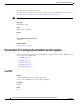
Chapter 5 Parameters and Defaults Parameters for Configuration Method and Encryption Default 1 Voice Configuration Menu Access Code 305 Related Parameters • TftpURL, page 5-5 • EncryptKey, page 5-6 • EncryptKeyEx, page 5-7 • OpFlags, page 5-34—bits 0 and 3 • CfgInterval, page 5-6 TftpURL Description Use this parameter to specify the IP address or URL of the TFTP server. This string is needed if the DHCP server does not provide the TFTP server IP address.
Chapter 5 Parameters and Defaults Parameters for Configuration Method and Encryption CfgInterval Description Use this parameter to specify the number of seconds between each configuration update. The Cisco ATA will also upgrade its signaling image if it detects that the TFTP server contains an upgraded image. For example, when using TFTP for configuration, the Cisco ATA contacts TFTP each time the interval expires to get its configuration file.
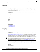
Chapter 5 Parameters and Defaults Parameters for Configuration Method and Encryption Range Maximum number of characters: 8 Default 0 Voice Configuration Menu Access Code 320 Related Parameters • UseTFTP, page 5-4 • TftpURL, page 5-5 • EncryptKeyEx, page 5-7 EncryptKeyEx Description This parameter specifies an encryption key that is stronger than the key specified with the EncryptKey parameter. This stronger key is used to encrypt the Cisco ATA configuration file on the TFTP server.
Chapter 5 Parameters and Defaults Network Configuration Parameters Value Type Hexadecimal string of the form: Rc4PasswdInHex/macinHex_12 • rc4KeyInHex_n is a hexadecimal string of one to 64 characters. • /macInHex_12 is the optional extension consisting of a forward slash ( / ) followed by the six-byte MAC address of the Cisco ATA to which the configuration file will be downloaded.
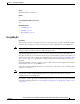
Chapter 5 Parameters and Defaults Network Configuration Parameters Value Type Boolean Range 0 or 1 Default 1 Voice Configuration Menu Access Code 20 Related Parameters • StaticIp, page 5-9 • StaticRoute, page 5-9 • StaticNetMask, page 5-10 • OpFlags, page 5-34—Bits 3 and 11 StaticIp Description Use this parameter to statically assign the Cisco ATA IP address if the DHCP parameter is set to 0. Value Type IP address Default 0.0.0.
Chapter 5 Parameters and Defaults Network Configuration Parameters Default 0.0.0.0 Voice Configuration Menu Access Code 2 Related Parameters • DHCP, page 5-8 • StaticIp, page 5-9 • StaticNetMask, page 5-10 StaticNetMask Description Use this parameter to statically assign the Cisco ATA subnet mask if the DHCP parameter is set to 0 Value Type IP address Default 255.255.255.
Chapter 5 Parameters and Defaults Network Configuration Parameters Default 0.0.0.0 Voice Configuration Menu Access Code 141 Related Parameters • AltNTPIP, page 5-11 • TimeZone, page 5-36 AltNTPIP Description This parameter is the alternate NTP IP address, if you want redundancy. You can set this parameter to 0 or point to the same NTPIP if only one NTP server exists. Value Type IP address Default 0.0.0.
Chapter 5 Parameters and Defaults Network Configuration Parameters DNS2IP Description This parameter is for setting the secondary domain name server (DNS) IP address, if the DHCP server does not provide one. If DHCP provides DNS2IP (if it is non-zero), this parameter overwrites the DHCP-supplied value. You cannot specify a port parameter. The Cisco ATA uses the default DNS port only. Value Type IP address Default 0.0.0.
Chapter 5 Parameters and Defaults H.323 Parameters H.323 Parameters This sections describes the following parameters, which include H.
Chapter 5 Parameters and Defaults H.323 Parameters GkId Description This parameter is the identifier for the primary H.323 gatekeeper. Value Type Alphanumeric string Default . (not specified) Range Maximum 31 characters Voice Configuration Menu Access Code 91 GkTimeToLive Description This parameter specifies the “time to live” value that is used when the Cisco ATA registers with the H.323 gatekeeper. The registration is valid until the configured time expires.
Chapter 5 Parameters and Defaults H.323 Parameters Range Maximum number of characters: 31 Default 0 Voice Configuration Menu Access Code 6 Related Parameter AltGkTimeOut, page 5-15 AltGkTimeOut Description You can use this parameter to specify the timeout in seconds before the Cisco ATA fails back to the primary gatekeeper from the backup gatekeeper. When the Cisco ATA switches to a different H.
Chapter 5 Parameters and Defaults H.323 Parameters UID0 Description This parameter is the User ID (E.164 phone number) for the Phone 1 port. If the value is set to zero, the port will be disabled and no dial tone will sound.
Chapter 5 Parameters and Defaults H.323 Parameters Voice Configuration Menu Access Code 4 Related Parameters • UID0, page 5-16 • UID1, page 5-17 • PWD1, page 5-18 • UseLoginID, page 5-19 • LoginID0, page 5-18 • LoginID1, page 5-19 • AutMethod, page 5-20 UID1 Description This parameter is the User ID (E.164 phone number) for the Phone 2 port. If the value is set to zero, the port will be disabled and no dial tone will sound.
Chapter 5 Parameters and Defaults H.323 Parameters PWD1 Description This parameter is the password for the Phone 2 port. Value Type Alphanumeric string Range Maximum number of characters: 31 Default 0 Voice Configuration Menu Access Code 14 Related Parameters • UID0, page 5-16 • UID1, page 5-17 • PWD0, page 5-16 • UseLoginID, page 5-19 • LoginID0, page 5-18 • LoginID1, page 5-19 • AutMethod, page 5-20 LoginID0 Description This parameter is the H.
Chapter 5 Parameters and Defaults H.323 Parameters Voice Configuration Menu Access Code 46 Related Parameters • LoginID1, page 5-19 • PWD0, page 5-16 • PWD1, page 5-18 • UseLoginID, page 5-19 • AutMethod, page 5-20 LoginID1 Description This parameter is the H.323 login ID for the Phone 2 port of the Cisco ATA. This value is used for registration and authentication if the UseLoginID parameter is set to 1.
Chapter 5 Parameters and Defaults H.
Chapter 5 Parameters and Defaults Audio Configuration Parameters Value Type Alphanumeric string Range Maximum number of characters: 31 Default 0 Voice Configuration Menu Access Code 11 Audio Configuration Parameters This section describes the following audio parameters, which allow you to configure such items as codecs and silence suppression: • MediaPort, page 5-21 • RxCodec, page 5-22 • TxCodec, page 5-22 • LBRCodec, page 5-23 • AudioMode, page 5-24 • NumTxFrames, page 5-25 • TOS, page
Chapter 5 Parameters and Defaults Audio Configuration Parameters Related Parameters • TOS, page 5-26 • VLANSetting, page 5-12 RxCodec Description Use this parameter to specify receiving-audio codec preference. The following values are valid: • 0—G.723 (can be selected only if LBRCodec is set to 0) • 1—G.711A-law • 2—G.711µ-law • 3—G.
Chapter 5 Parameters and Defaults Audio Configuration Parameters Range 0-3 Default 2 Voice Configuration Menu Access Code 37 Related Parameters • LBRCodec, page 5-23 • NumTxFrames, page 5-25 • RxCodec, page 5-22 • AudioMode, page 5-24 LBRCodec Description This parameter allows you to specify which low-bit-rate codecs are available. The Cisco ATA is capable of supporting two G.723.1 connections or one G.729 connection. When G.723.
Chapter 5 Parameters and Defaults Audio Configuration Parameters AudioMode Description This parameter represents the audio operating mode. The lower 16 bits are for the Phone 1 port, and the upper 16 bits are for the Phone 2 port. Table 5-1 on page 5-24 provides definitions for each bit.
Chapter 5 Parameters and Defaults Audio Configuration Parameters NumTxFrames Description Use this parameter to select the number of frames per packet that the Cisco ATA transmits: Note • The frame size for each G.729 data packet is 10 ms. • The frame size for each G.723 data packet is 30 ms. The frame size for G.711 is fixed at 20 ms per packet and is not configurable. Examples • To obtain 60 ms of G.723 audio, set the parameter value to 2. • To obtain 120 ms of G.
Chapter 5 Parameters and Defaults Operational Parameters TOS Description This parameter allows you to configure Type of Service (ToS) bits by specifying the precedence and delay of audio and signaling IP packets, as follows: • Bits 0-7—These bits are for the ToS value for voice data packets. Range: 0-255 Default: 184 • Bits 8-15—These bits are for the ToS value for signaling-data packets Range: 0-255 Default: 168 • Bits 16-31—Reserved.
Chapter 5 Parameters and Defaults Operational Parameters CallFeatures Description Disable/enable CallFeatures by setting each corresponding bit to 0 or 1. The lower 16 bits are for the Phone 1 port, and the upper 16 bits are for the Phone 2 port. Table 5-2 provides definitions of each bit. Note The subscribed features that can be permanently disabled by the user are CLIP_CLIR, call waiting and Fax mode.
Chapter 5 Parameters and Defaults Operational Parameters Table 5-2 CallFeatures Parameter Bit Definitions (continued) Bit Number Definition 12-14 and 28-30 Reserved. 15 and 31 Fax mode. This service allows the user to set the Cisco ATA to Fax mode on a per-call basis. For Fax mode, use the following settings: • G711 codec only • No silence suppression • No FAX tone detection PaidFeatures Description Unsubscribe/subscribe to CallFeatures by setting each corresponding bit to either 0 or 1.
Chapter 5 Parameters and Defaults Operational Parameters Table 5-3 PaidFeatures Parameter Bit Definitions (continued) Bit Number Definition 6 and 22 Not used for H.323. 7 and 23 Not used for H.323. 8 and 24 Caller ID. This service enables the Cisco ATA 186 to generate a Caller ID signal to drive a Caller ID display device attached to the FXS line. 9 and 25 Not used for H.323. 10 and 26 Not used for H.323. 11 and 27 Call Waiting Caller ID. 12-14 and 28-30 Reserved. 15 and 31 Fax mode.
Chapter 5 Parameters and Defaults Operational Parameters FeatureTimer Description This parameter provides configurable timing values for various telephone features, as described below: • Bits 1-15—Reserved. • Bits 16-18—Configurable call waiting ring timeout. When a call arrives for a Cisco ATA port that is in use and has call-waiting enabled, the Cisco ATA plays a call-waiting tone.
Chapter 5 Parameters and Defaults Operational Parameters FeatureTimer2 Description This parameter provides configurable timing values for various Cisco ATA features, as described below: • Bits 0-7—Maximum time that the Ethernet connection can be disconnected before the Cisco ATA automatically reboots. – Range: 0 - 255 – Factor: one-second increments – Values: 0 - 255 seconds – Default: 30 (equals 30 seconds) Note To disable this feature, set the value of bits 0-7 to 0.
Chapter 5 Parameters and Defaults Operational Parameters Table 5-4 SigTimer Parameter Bit Definitions Bit Number Definition 0-7 Call waiting period—The period between each burst of call-waiting tone. Range: 0 to 255 in 0.1 seconds Default: 100 (0x64=100 seconds) 8-13 Reorder delay—The delay in playing the reorder (fast busy) tone after the far-end caller hangs up. Range: 0 to 62 in seconds Default—5 (seconds) 63—Never play the reorder tone.
Chapter 5 Parameters and Defaults Operational Parameters Table 5-5 ConnectMode Parameter Bit Definitions Bit Number Definition 0 0—Use slow-start procedure (for H.225/Q.931 and H.245). 1—Use fast-start procedure (for H.225/Q.931). Default: 0 1 0/1—Disable/enable h245 tunneling. Default: 0 2 0—Use the dynamic payload type 126/127 as the RTP payload type (fax pass-through mode) for G.711 µ-law/G.711 A-law. 1—Use the standard payload type 0/8 as the RTP payload type (fax pass-through mode) for G.
Chapter 5 Parameters and Defaults Operational Parameters Table 5-5 ConnectMode Parameter Bit Definitions (continued) Bit Number Definition 16 0/1—Disable check-bearer capability in the received Q.931 Setup message. If this setting is enabled, the Cisco ATA returns the value 65 as the release-complete cause if the Information Transfer Capability (ITC) is “unrestricted digital information” or “restricted digital information.
Chapter 5 Parameters and Defaults Operational Parameters Table 5-6 OpFlags Parameter Operational Features to Turn On or Off Bit Number Definition 0 If Bit 0 = 0, the TFTP configuration filename supplied by the DHCP server overwrites the default filename for each Cisco ATA. If Bit 0 = 1, the default Cisco ATA filename is always used. Default: 0 1 If Bit 1 = 0, the Cisco ATA probes the static network router during the power-up process. If Bit 1 = 1, static network router probing is disabled.
Chapter 5 Parameters and Defaults Operational Parameters Table 5-6 OpFlags Parameter Operational Features to Turn On or Off (continued) Bit Number Definition 11 If Bit 11=0, the Cisco ATA requests the device hostname from the DHCP server. If Bit 11=1, the Cisco ATA uses the device hostname that is specified in DHCP option 12. Default: 0 12 Reserved. 13 DNS Servers For Name Resolution If Bit 13=0 (default), use statically configured DNS IP addresses, if available, for name resolution.
Chapter 5 Parameters and Defaults Telephone Configuration Parameters Value Type Integer Range 0-24 Default 17 Voice Configuration Menu Access Code 302 Additional Description Use the following list to select Timezone offset (in minutes) from GMT for the following cities and countries that have 30-minute-factor and 45-minute-factor time zone offsets. These values are integers and can range from -720 through -60, and from 60 through 780.
Chapter 5 Parameters and Defaults Telephone Configuration Parameters CallerIdMethod Description This 32-bit parameter specifies the signal format to use for both FXS ports for generating Caller ID format. Possible values are: • Bits 0-1 (method)—0=Bellcore (FSK), 1=DTMF, 2=ETSI, and 3 is reserved. If method=0 (default), set the following bits: • Bit 2—Reserved.
Chapter 5 Parameters and Defaults Telephone Configuration Parameters • Bit 16—If this bit is enabled (it is enabled by default), send special character P (private) to CID device if telephone number is restricted. • Bits 17-27 are reserved.
Chapter 5 Parameters and Defaults Telephone Configuration Parameters • Bit 3: CALLEE_DISCONNECT_POLARITY. Polarity to use when the Cisco ATA is the callee and the call is disconnected. – 0 =Use forward polarity (Default) – 1 =Use reverse polarity Note Bits 4-31 are reserved. Value Type Bitmap Default 0x00000000 Voice Configuration Menu Access Code 304 FXSInputLevel Description Use this parameter to specify the input level control (analog-to-digital path) of the Cisco ATA FXS ports.
Chapter 5 Parameters and Defaults Tone Configuration Parameters Range -9 to 2 dB Default -4 Voice Configuration Menu Access Code 371 Related Parameter FXSInputLevel, page 5-40 Tone Configuration Parameters The Cisco ATA supports the following tone parameters: • DialTone • BusyTone • ReorderTone • RingBackTone • CallWaitTone • AlertTone The Cisco ATA supports two types of tone-parameter syntax—basic format and extended format.
Chapter 5 Parameters and Defaults Tone Configuration Parameters • NumOfFreqs is the number of frequency components (0, 1 or 2). • Tfreq1 and Tfreq2 are the transformed frequencies of the first and second frequencies, respectively. Their values are calculated with the following formula: 32767 * cos (2*pi*F/8000) where F is the desired frequency in Hz. Set this value to 0 if the frequency does not exist. The range of each value is –32768 to 32767.
Chapter 5 Parameters and Defaults Tone Configuration Parameters Tone Parameter Syntax—Extended Formats Two types of extended format exist for the Cisco ATA tone parameters: • Extended Format A, page 5-43—This format can be used for the following tone parameters: – DialTone – BusyTone – RingbackTone – CallWaitTone – AlertTone • Extended Format B, page 5-44—This format can be used only for the ReorderTone parameter.
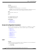
Chapter 5 Parameters and Defaults Tone Configuration Parameters • OffTime1 and OffTime2 values are the lengths of time that silence is played for the first and second on-off pairs of a cadence, respectively. (See Figure 5-1 for a graphical representation.) Specify each value as a number of samples with a sampling rate of 8 kHz. The range of each value is 0 to 0xffff. For example, for a length of 0.3 seconds, set the value to 2400.
Chapter 5 Parameters and Defaults Tone Configuration Parameters • TFreq1, TFreq2, and TFreq3 are the transformed frequencies of the first, second, and third frequencies, respectively. Calculate each value with the following formula: 32767 * cos (2 * pi * F/8000) where F is the desired frequency in Hz. Set this value to 0 if the frequency does not exist. The range of each value is –32768 to 32767. For negative values, use the 16-bit 2’s complement value. For example, enter –1 as 65535 or as 0xffff.
Chapter 5 Parameters and Defaults Tone Configuration Parameters Two examples of Extended Format B, both using the Reorder tone, follow. ReorderTone Parameter Example1 Assume that you want a reorder tone in which: • The frequencies 900 Hz, 1400 Hz, and 1800 Hz play sequentially. • Each frequency plays once for 0.33 seconds. • There is no silence after the first and the second frequencies.
Chapter 5 Parameters and Defaults Tone Configuration Parameters Table 5-7 Reorder Tone Parameter Example 1 Explanation (continued) Component Setting Explanation NumOfRepeats 0 First on-off pair of the cadence plays once (does not repeat), then the second on-off pair plays TotalToneTime 0 Tone plays continuously (set of three on-off pairs of the cadence repeat continuously) until another call event stops the tone ReorderTone Parameter Example 2 Assume that you want a reorder tone in which: • T
Chapter 5 Parameters and Defaults Tone Configuration Parameters Table 5-8 Reorder Tone Parameter Example 2 Explanation (continued) Component Setting Explanation NumOfRepeats 5 First on-off pair of the cadence plays six times (plays once and then repeats five times), then the second on-off pair plays TotalToneTime 0 Tone plays continuously (set of two on-off pairs of the cadence repeat continuously) until another call event stops the tone Recommended Values The following settings are recommende
Chapter 5 Parameters and Defaults Tone Configuration Parameters • Tfreq1—31538 • Tfreq2—30831 • Tamp1—1380 • Tamp2—1740 • Steady—1 • OnTime—0 • OffTime—0 • TotalToneTime—1000 Voice Configuration Menu Access Code 920 BusyTone Description The Cisco ATA plays the busy tone when the callee is busy.
Chapter 5 Parameters and Defaults Tone Configuration Parameters • Tamp2—1513 • Steady—0 • OnTime—2000 • OffTime—2000 • TotalToneTime—0 Voice Configuration Menu Access Code 922 RingbackTone Description The Cisco ATA plays the ring-back tone when the callee is being alerted by the called device.
Chapter 5 Parameters and Defaults Tone Configuration Parameters • OffTime—2400 • TotalToneTime—4800 Voice Configuration Menu Access Code 924 AlertTone Description The Cisco ATA plays the alert tone as a confirmation tone that a special event, such as call forwarding, is in effect.
Chapter 5 Parameters and Defaults Dial Plan Parameters Recommended Values: • United States —2,4,25 • Sweden — 1,5,25 Voice Configuration Menu Access Code 929 Dial Plan Parameters This section describes the configurable parameters related to dial plans: • DialPlan, page 5-52 • DialPlanEx, page 5-60 • IPDialPlan, page 5-60 DialPlan Description The programmable dial plan is designed for the service provider to customize the behavior of the Cisco ATA for collecting and sending dialed digits.
Chapter 5 Parameters and Defaults Dial Plan Parameters • Dial Plan Commands, page 5-53 • Dial Plan Rules, page 5-54 • Dial Plan Examples, page 5-58 Dial Plan Commands The following list contains commands that can be used to create you own dial plans: • . —Wildcard, match any digit entered. • - —Additional digits can be entered. This command can be used only at the end of a dial plan rule (for example, 1408t5- is legal usage of the - command, but 1408t5-3... is illegal).
Chapter 5 Parameters and Defaults Dial Plan Parameters Note No syntax check is performed by the actual implementation. The administrator has the responsibility of making sure that the dial plan is syntactically valid.
Chapter 5 Parameters and Defaults Dial Plan Parameters Syntax Hdnnnn where d is a delay-in-seconds parameter 0-9,a-z (to support 0 to 35 seconds delay), and nnnn is the variable-length phone number to call when no digits are entered for d seconds after offhook. Example 1 H05551212 This is a hotline configuration; the Cisco ATA immediately dials 555-1212 when the handset goes off hook.
Chapter 5 Parameters and Defaults Dial Plan Parameters Example 1 R1212([2_9]-) This rule prepends 1212 to dial strings that have a leading digit of 2 to 9. Note Note: ‘R’ rules can replace most ‘P’ rules; for example, Pn12345 is the same as R12345([1_9]-). Example 2 R-0033(0[1-9].r7) This removes the first dialed digit, then prepends 0033 to the dialed string. For example, if the number 0148336134 is dialed, the resulting string becomes 0033148336134. Example 3 R----0(0033[1-9].
Chapter 5 Parameters and Defaults Dial Plan Parameters Example: F1900|F1888 or F(1900|1888) These rules block call forwarding numbers beginning with 1900 or 1888. Log Information The CFWD Block: is shown in the prserv log, and a busy tone is being played. ‘X’ Rule for Call Blocking and Call Forwarding Blocking This rule is for blocking call numbers and call forwarding numbers.
Chapter 5 Parameters and Defaults Dial Plan Parameters Dial Plan Examples This section contains three dial plan examples that use many different rules and commands. Dial Plan Example 1 (Default Dial Plan) The following dial plan: *St4-|#St4-|911|1>#t8.r9t2-|0>#t811.rat4-|^1t4>#.- consists of the following rules: • *St4-—If the first digit entered is *, all other dial plan rules are voided.
Chapter 5 Parameters and Defaults Dial Plan Parameters Dial Plan Example 2 The following dial plans: .t7>#......t4-|911|1t7>#..........t1-|0t4>#.t7or .t7>#r6t4-|911|1t7>#.r9t1-|0t4>#.t7- consist of the following rules: • .t7>#r6t4-—You must enter at least one digit. After the first digit is entered and matched by the dial plan, the timeout before an automatic send is seven seconds, and the terminating character # can be entered at any time to manually send the dial string.
Chapter 5 Parameters and Defaults Diagnostic Parameters DialPlanEx If your dial plan exceeds 199 characters, then use must use the DialPlanEx parameter to configure your dial plans. The DialPlanEx parameter supports dial plans up to 499 characters in length. This range in the number of characters is the only difference between the DialPlanEx and DialPlan parameters. Therefore, all the information about the DialPlan parameter applies to the DialPlanEx parameter.
Chapter 5 Parameters and Defaults Diagnostic Parameters NPrintf Description Use this parameter to specify the IP address and port of a host to which all Cisco ATA debug messages are sent. The program prserv.exe, which comes bundled with the Cisco ATA software, is needed to capture the debug information. Syntax , Example If the program prserv.exe is running on a host with IP address 192.168.2.170 and listening port 9001, set NPrintf to 192.168.2.170.9001.
Chapter 5 Parameters and Defaults Diagnostic Parameters Voice Configuration Menu Access Code 7975640 Related Parameter SyslogCtrl, page 5-62 SyslogCtrl Description Use this parameter to turn on specific syslog traces. All traces are sent to the syslog server specified in the SyslogIP parameter. See Table 5-9 for bit values and the corresponding types of messages to turn on for tracing.
Chapter 5 Parameters and Defaults CFGID—Version Parameter for Cisco ATA Configuration File CFGID—Version Parameter for Cisco ATA Configuration File Description CFGID is a 32-bit unsigned-value parameter whose purpose is to allow the local administrator to track the version of the Cisco ATA configuration file. This parameter-value assignment is entirely the responsibility of the local administrator, and has no significance to the operation of the Cisco ATA.
Chapter 5 Parameters and Defaults CFGID—Version Parameter for Cisco ATA Configuration File Cisco ATA 186 and Cisco ATA 188 Analog Telephone Adaptor Administrator’s Guide for H.323 (version 3.