
User's Manual
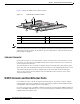
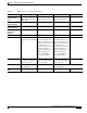
Table Of Contents

6-2
Cisco 3200 Series Router Hardware Reference
OL-5816-09
Chapter 6 Wireless Mobile Interface Cards (WMICs)
Figure 6-1 shows the WMIC header and bus locations.
Figure 6-1 WMIC Header and Bus Locations
Note The PC/104-Plus standard requires that the PCI bus and the ISA bus utilize keying features in the
standard stacking headers to guarantee proper module installation. On the PCI bus, pin D30 is removed
and the D30 opening is plugged. On the ISA bus, pin C19 and pin B10 are removed, and the C19 and
B10 openings are plugged.
Antenna Connector
On the radio card, there are two ultra-miniature coaxial connectors (U.FL connector) that are used to
connect the coax cables between the WMIC and the external antenna connectors. Two connectors are
used to support antenna diversity.
The cable should be as short as possible to minimize the loss in strength of the radio frequency (RF)
signal. The cable carries the RF signal from the antenna to the low noise amplifier (LNA) on the receiver
and transmits the RF signal from power amplifier (PA) to the antenna that radiates the RF signal.
There are many antenna connector families. The Cisco RP-TNC antenna connector can be used to
support standard antennas.
WMIC Console and Fast Ethernet Ports
Cisco 3200 Series router cards do not support any ISA bus signals. The PCI bus connector supports
communication between Cisco 3200 Series router card and the Fast Ethernet Switch Mobile Interface
Card (FESMIC) and Serial Mobile Interface Card (SMIC).
In a Cisco rugged enclosure, the WMIC communicates with the router through the WMIC Fast Ethernet
interface. The WMIC Fast Ethernet ports are connected internally to Fast Ethernet ports that provide a
communications link with the router.
1 PCI bus 2 Left antenna connector (J2)
3 Right antenna connector (J1) 4 ISA bus
5 10-pin Fast Ethernet header 6 24-pin multifunction header
103981
4
2
1
3
5
6