Cisco UCS C200 Server Installation and Service Guide Covers UCS C200 Server Generations M1 and M2 February 22, 2013 Americas Headquarters Cisco Systems, Inc. 170 West Tasman Drive San Jose, CA 95134-1706 USA http://www.cisco.
THE SPECIFICATIONS AND INFORMATION REGARDING THE PRODUCTS IN THIS MANUAL ARE SUBJECT TO CHANGE WITHOUT NOTICE. ALL STATEMENTS, INFORMATION, AND RECOMMENDATIONS IN THIS MANUAL ARE BELIEVED TO BE ACCURATE BUT ARE PRESENTED WITHOUT WARRANTY OF ANY KIND, EXPRESS OR IMPLIED. USERS MUST TAKE FULL RESPONSIBILITY FOR THEIR APPLICATION OF ANY PRODUCTS.
CONTENTS Preface vii Related Documentation Audience vii vii Organization vii Conventions viii Obtaining Documentation and Submitting a Service Request CHAPTER 1 Overview CHAPTER 2 Installing the Server xiii 1-1 2-1 Unpacking and Inspecting the Server Preparing for Installation 2-3 Installation Guidelines 2-3 Rack Requirements 2-4 Required Equipment 2-4 Slide Rail Adjustment Range Installing the Server Into a Rack 2-2 2-4 2-5 Initial Server Setup 2-9 Connecting and Powering On the Serve
Contents Status LEDs 3-2 Front Panel LEDs Rear Panel LEDs 3-2 3-4 Preparing for Component Installation 3-7 Required Equipment 3-7 Shutting Down and Powering Off the Server 3-7 Removing and Replacing the Server in a Rack 3-8 Removing and Replacing the Server Top Cover 3-9 Removing and Replacing the Server Front Cover (Small Form Factor Only) Replaceable Component Locations 3-11 3-10 Installing or Replacing Components 3-13 Replacing a Front Panel Control Module or DVD Module (Small Form Factor Only) 3-14
Contents Supported Power Cords and Plugs B-2 AC Power Cord Illustrations B-3 APPENDIX C RAID Controller Considerations C-1 Supported RAID Controllers and Required Cables C-1 Enabling the Integrated Intel ICH10R RAID Controller in the BIOS Enabling the Mezzanine Card RAID Controller in the BIOS RAID Controller Cabling C-3 Cisco UCS C200 LFF Server Cabling Cisco UCS C200 SFF Server Cabling C-2 C-3 C-4 C-4 How to Determine Which Controller Is in Your Server C-4 How to Disable Quiet Boot For CIMC
Contents Cisco UCS C200 Server Installation and Service Guide vi OL-20732-02
Preface This preface describes the audience, organization, and conventions of the Cisco UCS C200 Server Installation and Service Guide. It also provides information on how to obtain related documentation. This guide covers UCS C200 Server Generations M1 and M2. Differences between the generations are noted in text.
Preface Conventions This document uses the following conventions for notes, cautions, and safety warnings. Notes and Cautions contain important information that you should know. Note Means reader take note. Notes contain helpful suggestions or references to material that are not covered in the publication. Caution Means reader be careful. You are capable of doing something that might result in equipment damage or loss of data.
Preface Attention IMPORTANTES INFORMATIONS DE SÉCURITÉ Ce symbole d'avertissement indique un danger. Vous vous trouvez dans une situation pouvant entraîner des blessures ou des dommages corporels. Avant de travailler sur un équipement, soyez conscient des dangers liés aux circuits électriques et familiarisez-vous avec les procédures couramment utilisées pour éviter les accidents.
Preface ¡Advertencia! INSTRUCCIONES IMPORTANTES DE SEGURIDAD Este símbolo de aviso indica peligro. Existe riesgo para su integridad física. Antes de manipular cualquier equipo, considere los riesgos de la corriente eléctrica y familiarícese con los procedimientos estándar de prevención de accidentes. Al final de cada advertencia encontrará el número que le ayudará a encontrar el texto traducido en el apartado de traducciones que acompaña a este dispositivo.
Preface Aviso INSTRUÇÕES IMPORTANTES DE SEGURANÇA Este símbolo de aviso significa perigo. Você se encontra em uma situação em que há risco de lesões corporais. Antes de trabalhar com qualquer equipamento, esteja ciente dos riscos que envolvem os circuitos elétricos e familiarize-se com as práticas padrão de prevenção de acidentes. Use o número da declaração fornecido ao final de cada aviso para localizar sua tradução nos avisos de segurança traduzidos que acompanham o dispositivo.
Preface Cisco UCS C200 Server Installation and Service Guide xii OL-20732-02
Preface Obtaining Documentation and Submitting a Service Request For information on obtaining documentation, submitting a service request, and gathering additional information, see the monthly What’s New in Cisco Product Documentation, which also lists all new and revised Cisco technical documentation, at: http://www.cisco.com/en/US/docs/general/whatsnew/whatsnew.
Preface Cisco UCS C200 Server Installation and Service Guide xiv OL-20732-02
CH A P T E R 1 Overview The Cisco UCS C200 Server, which is a part of the Cisco UCS C-Series Rack-Mount server family, is designed to operate in a wide range of data center environments, including those environments that use the Cisco Unified Computing System, Cisco Nexus family products, and discrete Ethernet and Fibre Channel switches from Cisco and third parties. The Cisco UCS C200 server is a high-density, two-socket, 1RU rack-mount server designed to balance simplicity, performance, and density.
Chapter 1 Figure 1-2 Overview Front Panel Features, Small Form Factor 7 6 5 4 3 1 9 8 2 11 12 13 -A- 17 14 16 310369 18 10 15 1 KVM console connector 10 Hard drives (up to 8) 2 Reset button1 11 Hard drive fault LED 3 Power supply fault LED 12 Hard drive activity LED 4 Memory fault LED 13 Optional DVD module 5 CPU fault LED 14 DVD activity LED 6 Network activity LED 15 Power button/Power status LED 7 System fault LED 16 Locator button/LED 8 Locator button/LED 17 Reset b
Chapter 1 Overview Figure 1-3 shows the external features of the rear panel. A Generation M2 server is shown (the USB ports and the 10/100 Ethernet management port are in slightly different positions for Generation M1). Rear Panel Features 1 4 2 8 7 5 253037 Figure 1-3 M 2 1/M 3 6 1 Power supply (up to two) 5 Video connector (DB15 VGA) 2 10/100 Ethernet management port (RJ-45) 6 10/100/1000 Gigabit Ethernet ports (two) 3 USB 2.
Chapter 1 Overview The Cisco UCS C200 server has the following components and features. Differences between the Large Form Factor (LFF) version of the server (PID R200-1120402W) and the Small Form Factor (SFF) version of the server (PID UCS-BSE-SFF-C200) are noted. . Table 1-1 Hardware Features of the Server Feature or Component Cisco UCS C200 Server Enclosure Single rack unit (1RU) chassis. Processors Up to two quad-core Intel Xeon processors.
Chapter 1 Overview Table 1-1 Hardware Features of the Server (continued) Feature or Component Cisco UCS C200 Server Disk Management Factory-configured RAID9 support options, which differ for the LFF and SFF versions of the server. • LFF: – RAID 0 and 1 support for up to 4 SATA drives with the integrated SATA controller. The integrated ICH10R RAID controller is not compatible for use with VMWare ESX/ESXi Server software in any generation or version of the Cisco UCS C200 server.
Chapter 1 Overview 9. RAID = redundant array of independent disks See Appendix A, “Technical Specifications” for more physical, environmental, and power details.
CH A P T E R 2 Installing the Server This chapter describes how to install the server and includes the following sections: Note Warning • Unpacking and Inspecting the Server, page 2-2 • Preparing for Installation, page 2-3 • Installing the Server Into a Rack, page 2-5 • Initial Server Setup, page 2-9 • System BIOS and CIMC Firmware, page 2-13 Before you install, operate, or service a server, review the Regulatory Compliance and Safety Information for Cisco UCS C-Series Servers for important s
Chapter 2 Installing the Server Unpacking and Inspecting the Server Unpacking and Inspecting the Server Tip Keep the shipping container in case the server requires shipping in the future. Note The chassis is thoroughly inspected before shipment. If any damage occurred during transportation or any items are missing, contact your customer service representative immediately. To inspect the shipment, follow these steps: Step 1 Remove the server from its cardboard container—save all packaging material.
Chapter 2 Installing the Server Preparing for Installation Preparing for Installation This section includes the following topics: • Installation Guidelines, page 2-3 • Rack Requirements, page 2-4 • Required Equipment, page 2-4 Installation Guidelines Warning To prevent the system from overheating, do not operate it in an area that exceeds the maximum recommended ambient temperature of: 35° C (95° F).
Chapter 2 Installing the Server Preparing for Installation Rack Requirements This section provides the requirements for the standard open racks, assuming an external ambient air temperature range of 32 to 95F (0 to 35C). The rack must be of the following type: • Standard 19-inch (48.3-cm) wide, four-post EIA rack, with mounting posts that conform to English universal hole spacing per section 1 of ANSI/EIA-310-D-1992. • The rack post holes can be square or round when you use the supplied slide rails.
Chapter 2 Installing the Server Installing the Server Into a Rack Installing the Server Into a Rack The qualified and supported part numbers for this component are subject to change over time. For the most up-to-date list of replaceable components, see the following URL and then scroll to Technical Specifications: http://www.cisco.com/en/US/products/ps10493/products_data_sheets_list.html This section describes how to install the server into a rack.
Chapter 2 Installing the Server Installing the Server Into a Rack Figure 2-2 Attaching a Slide-Rail Assembly 1 2 3 5 6 195968 4 Note 1 Front-left rack post 4 Length-adjustment bracket 2 Rear-left rack post 5 Locking clip (one on each end of assembly) 3 Slide-rail assembly 6 Mounting pegs (two on each end of assembly) The mounting pegs that protrude through the rack-post holes are designed to fit round or square #12-24 holes, or #10-32 holes when the mounting peg is compressed (see Fi
Chapter 2 Installing the Server Installing the Server Into a Rack Tip Step 2 Tip d. Attach the second slide-rail assembly to the opposite side of the rack. Ensure that the two slide-rail assemblies are level and at the same height with each other. e. Pull the inner slide rails on each assembly out toward the rack front until they hit the internal stops and lock in place. You can optionally use the #2 Phillips screws that come with the slide rails to increase stability after installation.
Chapter 2 Installing the Server Installing the Server Into a Rack Step 4 Attach the (optional) cable management arm (CMA) to the rear of the slide rails: Note The orientation in these instructions refers to a view from the front of the server. a. Slide the plastic clip on the right end of the CMA length-adjustment slider (item 2) into the rear of the right slide rail (item 1) until it clips onto the plastic retaining flange inside the slide rail. See Figure 2-5. b.
Chapter 2 Installing the Server Initial Server Setup Initial Server Setup This section contains the following topics: • Connecting and Powering On the Server (Standalone Mode), page 2-9 • NIC Modes and NIC Redundancy Settings, page 2-12 Connecting and Powering On the Server (Standalone Mode) Note This section describes how to power on the server, assign an IP address, and connect to server management when using the server in standalone mode.
Chapter 2 Installing the Server Initial Server Setup Step 2 Use the supplied KVM cable to connect a keyboard and VGA monitor to the console connector on the front panel (see Figure 1-1 on page 1-1 or Figure 1-2 on page 1-2). Note Alternatively, you can use the VGA and USB ports on the rear panel. However, you cannot use the front panel console connector VGA and the rear panel VGA at the same time.
Chapter 2 Installing the Server Initial Server Setup d. Use this utility to change the NIC redundancy to your preference. This server has three possible NIC redundancy settings: – None—The Ethernet ports operate independently and do not fail over if there is a problem. – Active-standby—If an active Ethernet port fails, traffic fails over to a standby port. – Active-active—All Ethernet ports are utilized simultaneously. e. Note f. Note g.
Chapter 2 Installing the Server Initial Server Setup NIC Modes and NIC Redundancy Settings This server has the following NIC mode settings that you can choose from: • Dedicated—The 10/100 dedicated management port is used to access the CIMC. You have to select a NIC redundancy and IP setting. • Shared LOM (default)—The two 1Gb Ethernet ports are used to access the CIMC. This is the factory default setting, along with Active-active NIC redundancy and DHCP enabled.
Chapter 2 Installing the Server System BIOS and CIMC Firmware System BIOS and CIMC Firmware This section contains information about the system BIOS and it includes the following sections: • Updating the BIOS and CIMC Firmware, page 2-13 • Accessing the System BIOS, page 2-14 Updating the BIOS and CIMC Firmware Caution When you upgrade the BIOS firmware, you must also upgrade the CIMC firmware to the same version or the server will not boot.
Chapter 2 Installing the Server System BIOS and CIMC Firmware Accessing the System BIOS You can change the BIOS settings for your server by using the procedure in this section. Detailed instructions are also printed on the BIOS screens. Step 1 Enter the BIOS setup utility by pressing the F2 key when prompted during bootup. Note The version and build of the current BIOS are displayed on the Main page of the utility. Step 2 Use the arrow keys to select the BIOS menu page.
Chapter 2 Installing the Server System BIOS and CIMC Firmware Motherboard Jumpers These jumpers are adjacent to the CMOS battery (see Figure 2-6).
Chapter 2 Installing the Server System BIOS and CIMC Firmware Using the BIOS Recovery Jumper J1E5 to Recover Corrupt BIOS This jumper is adjacent to the CMOS battery (see Figure 2-6). You can use this jumper to force the server to flash a new BIOS, in the case of a system hang. For example, if the system hangs after a BIOS update, use this procedure to force the server to look for the new firmware. Step 1 Download the BIOS update package and extract it to a temporary location.
Chapter 2 Installing the Server System BIOS and CIMC Firmware Clearing the CIMC Admin Password Using Jumper J45 This procedure describes how to clear the CIMC admin password back to the default in case the user-selected password is lost of forgotten. Step 1 Power off the server as described in the “Shutting Down and Powering Off the Server” section on page 3-7. Step 2 Disconnect all power cords from the power supplies.
Chapter 2 Installing the Server System BIOS and CIMC Firmware Using the Clear CMOS Jumper J1E6 You can use this jumper to clear the server’s CMOS settings in the case of a system hang. For example, if the server hangs because of incorrect settings and does not boot, use this jumper to invalidate the settings and reboot with defaults. Step 1 Power off the server as described in the “Shutting Down and Powering Off the Server” section on page 3-7.
Chapter 2 Installing the Server System BIOS and CIMC Firmware Clearing the BIOS Admin Password Using Jumper J1E4 This procedure describes how to clear the BIOS admin password for the BIOS back to the default in case the user-selected password is lost of forgotten. Step 1 Power off the server as described in the “Shutting Down and Powering Off the Server” section on page 3-7. Step 2 Disconnect all power cords from the power supplies.
Chapter 2 Installing the Server System BIOS and CIMC Firmware Cisco UCS C200 Server Installation and Service Guide 2-20 OL-20732-02
CH A P T E R 3 Maintaining the Server This chapter describes how to diagnose hardware problems with status LEDs and how to install or replace hardware components, and includes the following sections: • Server Monitoring and Management Tools, page 3-1 • Status LEDs, page 3-2 • Preparing for Component Installation, page 3-7 • Installing or Replacing Components, page 3-13 Server Monitoring and Management Tools Cisco Integrated Management Interface (CIMC) You can monitor the server inventory, health,
Chapter 3 Maintaining the Server Status LEDs Status LEDs This section describes the locations and interpretations of LEDs on the server that can provide status and troubleshooting information. This section includes the following topics: • Front Panel LEDs, page 3-2 • Rear Panel LEDs, page 3-4 Front Panel LEDs The front panel LEDs and their locations differ, depending on whether you have the Large Form Factor (LFF) or the Small Form Factor (SFF) version of the server.
Chapter 3 Maintaining the Server Status LEDs Figure 3-2 Front Panel LEDs (Small Form Factor) 5 4 3 2 1 7 6 8 9 10 14 13 12 239131 -A- 11 1 Power supply fault LED 8 Hard drive fault LED 2 Memory fault LEDs 9 Hard drive activity LED 3 CPU fault LED 10 Optional DVD module 4 Network activity LED 11 DVD activity LED 5 System fault LED 12 Power status LED/Power button 6 Locator LED/Locator button 13 Locator LED/Locator button 7 Power status LED/Power button 14 System fault LED T
Chapter 3 Maintaining the Server Status LEDs Table 3-1 Front Panel LEDs (continued) LED Name State CPU fault Network activity System fault Locator Power status • Off—All CPUs are operating properly. • Amber—At least one CPU has failed. • Off—The server is powered off or in standby power mode. • Green, blinking—The server is communicating with the network in main power mode. The blink rate is faster as network activity increases. • Green—The server is operating properly.
Chapter 3 Maintaining the Server Status LEDs Table 3-2 describes the possible states and interpretations for the LEDs that are shown in Figure 3-3. Table 3-2 Rear Panel LEDs LED Name State Power supply status • Off—No AC power is present in any power supplies. • Green—This power supply is operating properly in main power mode. • Green, blinking—This power supply is operating properly in standby power mode. • Amber, flashing—There is no AC power present in this power supply.
Chapter 3 Maintaining the Server Status LEDs Table 3-2 Rear Panel LEDs (continued) LED Name State Note The 10/100/1000 Gigabit Ethernet link status LED and the speed LED must be read in combination for the following interpretations. 10/100/1000 Gigabit Ethernet speed (left) 10/100/1000 Gigabit Ethernet link status (right) • Link status off + speed off—No link is present on this port. • Link status off + speed solid green—A half-duplex, 10-Mbps link is present.
Chapter 3 Maintaining the Server Preparing for Component Installation Preparing for Component Installation This section describes how to prepare the server for component installation and includes the following topics: • Required Equipment, page 3-7 • Shutting Down and Powering Off the Server, page 3-7 • Removing and Replacing the Server in a Rack, page 3-8 • Removing and Replacing the Server Top Cover, page 3-9 • Removing and Replacing the Server Front Cover (Small Form Factor Only), page 3-10 •
Chapter 3 Maintaining the Server Preparing for Component Installation Step 1 Step 2 Caution Step 3 Check the color of the Power Status LED (see the “Front Panel LEDs” section on page 3-2). • Green indicates that the server is in main power mode and must be shut down before it can be safely powered off. Go to Step 2. • Amber indicates that the server is already in standby mode and can be safely powered off. Go to Step 3.
Chapter 3 Maintaining the Server Preparing for Component Installation Removing and Replacing the Server Top Cover To remove or replace the server top cover, follow these steps: Tip Step 1 This unit might have more than one power cord. To reduce the risk of electric shock, disconnect the two power supply cords before servicing the unit. Statement 14 You do not have to remove the cover to replace hard drives or power supplies. Remove the top cover: a.
Chapter 3 Maintaining the Server Preparing for Component Installation Removing and Replacing the Server Front Cover (Small Form Factor Only) Note It is not necessary to remove the front cover unless instructed to do so in a replacement procedure. To remove or replace the front cover of the SFF version of the server (PID UCSC-BSE-SFF-C200), follow these steps: Step 1 Step 2 Remove a front cover: a. Remove the server top cover, as described in Removing and Replacing the Server Top Cover, page 3-9. b.
Chapter 3 Maintaining the Server Preparing for Component Installation Replaceable Component Locations This section shows the locations of the components that are discussed in this chapter. The view shown is from the top down, with the top cover, internal cable cover, and internal air baffles removed. • Figure 3-6 shows the Large Form Factor (LFF) version of the server. • Figure 3-7 on page 3-12 shows the Small Form Factor (SFF) version of the server.
Chapter 3 Maintaining the Server Preparing for Component Installation Figure 3-7 Replaceable Component Locations, Small Form Factor (Top View) 8 9 10 11 12 7 6 13 5 4 310370 3 2 1 1 Hard drives (up to eight, accessible through front bays) 7 PCIe card connector on riser card (with standard-profile slot) 2 Front panel control module or optional DVD module 8 Riser card assembly 3 Fan tray 9 PCIe card connector on riser card (with low-profile slot) 4 DIMM slots (up to 12) 10 Socket for
Chapter 3 Maintaining the Server Installing or Replacing Components Installing or Replacing Components Warning This unit might have more than one power cord. To reduce the risk of electric shock, disconnect the two power supply cords before servicing the unit.
Chapter 3 Maintaining the Server Installing or Replacing Components Replacing a Front Panel Control Module or DVD Module (Small Form Factor Only) The Small Form Factor version of the server (PID UCSC-BSE-SFF-C200) can contain a replaceable front panel control module or an optional DVD module in its place. This section describes how to replace a front panel control module or a DVD module. The qualified and supported part numbers for this component are subject to change over time.
Chapter 3 Maintaining the Server Installing or Replacing Components Note The rear edge of the front cover should go under the black plastic cable cover. f. Replace the top cover as described in the “Removing and Replacing the Server Top Cover” section on page 3-9. g. Replace the server in the rack, replace power cords and any other cables, and then power on the server by pressing the Power button.
Chapter 3 Maintaining the Server Installing or Replacing Components Alternate Front Panel Module Cable Routing Motherboard Front USB Front panel Motherboard Front USB Front COM Front VGA SATA CONN Fans Front panel control module 1 Securing screw (one on each end) 2 Fan tray with battery unit bracket Front COM Front VGA SATA CONN Fans Front panel 282336 Figure 3-9 DVD module 3 Fan tray connector Cisco UCS C200 Server Installation and Service Guide 3-16 OL-20732-02
Chapter 3 Maintaining the Server Installing or Replacing Components Installing Hard Drives or Solid State Drives The qualified and supported part numbers for this component are subject to change over time. For the most up-to-date list of replaceable components, see the following URL and then scroll to Technical Specifications: http://www.cisco.com/en/US/products/ps10493/products_data_sheets_list.
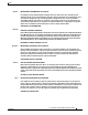
Chapter 3 Maintaining the Server Installing or Replacing Components – If you have the LFF version of the server with 3.5-in drives, the four screws install on the bottom of the sled. – If you have the SFF version of the server with 2.5-in drives, two screws install on each side of the sled. c. With the ejector lever still open, push the sled into the drive bay until you feel the drive stop against the backplane. d. Press the ejector lever flat until the lock clicks into place.
Chapter 3 Maintaining the Server Installing or Replacing Components Figure 3-12 Drive Numbering and Physical Orientation, Facing Server Front (Small Form Factor) HDD_04 Figure 3-13 HDD_05 HDD_01 HDD_02 HDD_03 HDD_06 HDD_07 HDD_08 Removing and Replacing Hard Drives (Small Form Factor) 2 282337 1 3 3 3 3 1 Ejector lever 2 Release button 3 Securing screws (four) Cisco UCS C200 Server Installation and Service Guide OL-20732-02 3-19
Chapter 3 Maintaining the Server Installing or Replacing Components Installing Power Supplies The qualified and supported part numbers for this component are subject to change over time. For the most up-to-date list of replaceable components, see the following URL and then scroll to Technical Specifications: http://www.cisco.com/en/US/products/ps10493/products_data_sheets_list.
Chapter 3 Maintaining the Server Installing or Replacing Components Installing a Fan Tray The qualified and supported part numbers for this component are subject to change over time. For the most up-to-date list of replaceable components, see the following URL and then scroll to Technical Specifications: http://www.cisco.com/en/US/products/ps10493/products_data_sheets_list.html To replace a fan tray, follow these steps: Step 1 Remove a fan tray: a.
Chapter 3 Maintaining the Server Installing or Replacing Components Figure 3-15 Removing and Replacing a Fan Tray 1 2 3 1 Securing screw (one on each end) 2 Fan tray with battery unit bracket 3 Fan tray connector Cisco UCS C200 Server Installation and Service Guide 3-22 OL-20732-02
Chapter 3 Maintaining the Server Installing or Replacing Components Installing DIMMs This section includes the following sections: Note • Memory Performance Guidelines and Population Rules, page 3-23 • DIMM Installation Procedure, page 3-26 To ensure the best server performance, it is important that you are familiar with memory performance guidelines and population rules before you install or replace memory modules.
Chapter 3 Maintaining the Server Installing or Replacing Components Figure 3-16 Physical Representation of Banks and Channels Rear of Server CPU 1 A2 A1 B2 B1 C2 C1 F1 F2 E1 E2 D1 D2 Front of Server 332177 CPU 2 Memory Population Rules When considering the memory configuration of your server, you should consider the following items: • DIMMs within the server should all be the same type, speed, and size. Do not mix different size DIMMs or DIMMs with different clock rates in the same server.
Chapter 3 Maintaining the Server Installing or Replacing Components Low-Voltage DIMM Considerations (Generation M2 Only) The Generation M2 of this server can be ordered with low-voltage (1.35 V) DIMMs or standard-voltage (1.5 V) DIMMs. Note the following considerations: • Low-voltage DIMMs within the server must have the identical manufacturer, type, speed, and size. • Low-voltage DIMMs and standard-voltage DIMMs can be mixed in the same server.
Chapter 3 Maintaining the Server Installing or Replacing Components DIMM Installation Procedure To install or replace a DIMM, follow these steps: Note Step 1 Refer to the DIMM population rules before removing or installing DIMMs. See the “Memory Performance Guidelines and Population Rules” section on page 3-23. Remove an existing DIMM: a. Power off the server as described in the “Shutting Down and Powering Off the Server” section on page 3-7. b. Disconnect all power cords from the power supplies.
Chapter 3 Maintaining the Server Installing or Replacing Components Figure 3-17 Removing and Replacing Memory Modules 1 3 195728 2 1 DIMM slots (twelve) 2 DIMM slot ejector lever (two on each slot) 3 Alignment key in DIMM slot Cisco UCS C200 Server Installation and Service Guide OL-20732-02 3-27
Chapter 3 Maintaining the Server Installing or Replacing Components Installing CPUs and Heatsinks The qualified and supported part numbers for this component are subject to change over time. For the most up-to-date list of replaceable components, see the following URL and then scroll to Technical Specifications: http://www.cisco.com/en/US/products/ps10493/products_data_sheets_list.html To install or replace a CPU and heatsink, follow these steps: Step 1 Remove an existing CPU and heatsink: a.
Chapter 3 Maintaining the Server Installing or Replacing Components Figure 3-18 Removing and Replacing CPUs and Heatsinks 3 4 2 1 195729 1 1 Captive heatsink screws (two per CPU) 3 CPU socket alignment keys 2 CPU cover plate 4 CPU socket latch Cisco UCS C200 Server Installation and Service Guide OL-20732-02 3-29
Chapter 3 Maintaining the Server Installing or Replacing Components Installing a Motherboard CMOS Battery Warning There is danger of explosion if the battery is replaced incorrectly. Replace the battery only with the same or equivalent type recommended by the manufacturer. Dispose of used batteries according to the manufacturer’s instructions. (Statement 1015) The qualified and supported part numbers for this component are subject to change over time.
Chapter 3 Maintaining the Server Installing or Replacing Components Figure 3-19 Removing and Replacing a Motherboard CMOS Battery 2 + 1 1 Motherboard CMOS battery socket (positive side toward chassis wall) 2 Battery retaining clip Installing a Trusted Platform Module The qualified and supported part numbers for this component are subject to change over time. For the most up-to-date list of replaceable components, see the following URL and then scroll to Technical Specifications: http://www.cisco.
Chapter 3 Maintaining the Server Installing or Replacing Components c. Replace the PCIe riser card assembly. See the “Replacing a PCIe Riser Card Assembly” section on page 3-33 for instructions. Note d. Replace the top cover. e. Replace the server in the rack, replace power cords and any other cables, and then power on the server by pressing the Power button. See the following note. The TPM must be activated in the BIOS before you can use it.
Chapter 3 Maintaining the Server Installing or Replacing Components h. On the BIOS utility screen, select the Security tab. i. Scroll down to TPM and select TURN ON. j. Press F10 to save your settings and reboot the server. k. Watch during bootup for the F2 prompt, and then press F2 to enter BIOS setup. l. Log into the BIOS Setup utility with your BIOS Administrator password. m. Verify that the TPM is now enabled. Select the Security tab. Verify that the TPM entry now says Enabled.
Chapter 3 Maintaining the Server Installing or Replacing Components Figure 3-21 Removing and Replacing a PCIe Riser Card Assembly 1 2 1 1 Riser card assembly (top view) 2 Riser card Replacing a PCIe Card This section contains the following topics: • Replacement Procedure, page 3-35 • Special Considerations for the Cisco UCS P81E Virtual Interface Card (N2XX-ACPCI01), page 3-37 • How to Identify Which Power Supply Model is in Your Server, page 3-37 • Installing Multiple PCIe Cards and Resol
Chapter 3 Maintaining the Server Installing or Replacing Components Replacement Procedure Installing a PCIe card requires that you first remove the riser card assembly from the chassis. To install or replace a PCIe card, follow these steps: Step 1 Remove a PCIe card: a. Power off the server as described in the “Shutting Down and Powering Off the Server” section on page 3-7. b. Disconnect all power cords from the power supplies. c.
Chapter 3 Maintaining the Server Installing or Replacing Components Figure 3-22 PCIe Slot Numbering and Physical Orientation, Facing Server Rear PCIe Slot 7 Figure 3-23 PCIe Slot 6 Removing and Replacing a PCIe Card 1 3 4 330739 2 1 Riser card assembly removed from chassis 3 PCIe card rear plate 2 PCIe socket on riser card 4 PCIe card retaining latch Cisco UCS C200 Server Installation and Service Guide 3-36 OL-20732-02
Chapter 3 Maintaining the Server Installing or Replacing Components Special Considerations for the Cisco UCS P81E Virtual Interface Card (N2XX-ACPCI01) The Cisco UCS P81E Virtual Interface Card is a standard-profile, half-length, dual-port 10 Gb PCIe card with SFP+. See the following special considerations and prerequisites: • This card is supported in server Generations M1 and M2. • This server supports installation of one of these cards. • This card is supported only in PCIe slot 6 of this server.
Chapter 3 Maintaining the Server Installing or Replacing Components Installing Multiple PCIe Cards and Resolving Limited Resources When a large number of PCIe add-on cards are installed in the server, the system may run out of the following resources required for PCIe devices: • Option ROM memory space • 16-bit I/O space The topics in this section provide guidelines for resolving the issues related to these limited resources.
Chapter 3 Maintaining the Server Installing or Replacing Components Resolving Insufficient 16-Bit I/O Space The system has only 64 KB of legacy 16-bit I/O resources available. This 64 KB of I/O space is divided between the CPUs in the system because the PCIe controller is integrated into the CPUs.
Chapter 3 Maintaining the Server Installing or Replacing Components Replacing an LSI MegaRAID Battery Backup Unit When you install an LSI MegaRAID card and the optional BBU in this server, do not install the BBU on top of the card as described in the LSI instructions. To avoid overheating the card, you must install the BBU on a special bracket that is located on the fan tray. Note LSI recommends that you replace the LSI BBU once per year or after 1,000 recharge cycles, whichever comes first.
Chapter 3 Maintaining the Server Installing or Replacing Components Note Step 3 Be careful to align the arrow-mark on the cable connector with the arrow-mark on the socket to avoid damaging the connector pins. b. Place the new BBU over the BBU bracket on the fan tray and align the three screw-holes in the BBU with the three preinstalled standoffs on the bracket. c. Replace the three securing screws that hold the BBU to the BBU bracket.
Chapter 3 Maintaining the Server Installing or Replacing Components Replacing an LSIiBBU08 BBU This BBU is supported by Cisco for use with the following RAID controller cards: • LSI MegaRAID 9260-4i (Cisco product ID R200-PL004, LSI 6G MegaRAID 9260-4i card w/512MB write cache) • LSI MegaRAID 9280-4i4e (Cisco product ID UCSC-RAID-C-4i4e, LSI 9280-4i4e) • LSI MegaRAID 9260-8i (Cisco product ID RC460-PL001, LSI 6G MegaRAID 9260-8i (C200 SFF only)) To install the LSIiBBU08 BBU, you must replace the mo
Chapter 3 Maintaining the Server Installing or Replacing Components Figure 3-26 Replacing a Mounting Bracket for the LSIiBBU08 BBU (Enlarged) 331002 Screws Step 2 Note Install the new LSIiBBU08 BBU: The LSIiBBU08 BBU requires minimum LSI MegaRAID card firmware 2.120.133.1322 or later to be recognized. You can use the Cisco Host Upgrade Utility to upgrade your LSI MegaRAID card firmware. Obtain the Cisco Host Upgrade Utility 1.4.1 or later package (including drivers) by navigating from the Cisco.
Chapter 3 Maintaining the Server Installing or Replacing Components Figure 3-27 Removing and Replacing an LSIiBBU06 BBU 2 3 331003 1 1 BBU bracket on fan tray 2 Securing screws (two) 3 BBU (connector J2 is on the underside) Cisco UCS C200 Server Installation and Service Guide 3-44 OL-20732-02
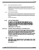
Chapter 3 Maintaining the Server Installing or Replacing Components Installing a Mezzanine Card The qualified and supported part numbers for this component are subject to change over time. For the most up-to-date list of replaceable components, see the following URL and then scroll to Technical Specifications: http://www.cisco.com/en/US/products/ps10493/products_data_sheets_list.html To install or replace a mezzanine card, follow these steps: Step 1 Remove a mezzanine card: a.
Chapter 3 Maintaining the Server Installing or Replacing Components Figure 3-28 Removing and Replacing a Mezzanine Card 1 195954 2 1 Mezzanine card retaining posts (three) 2 Mezzanine card Cisco UCS C200 Server Installation and Service Guide 3-46 OL-20732-02
A P P E N D I X A Technical Specifications This appendix lists the technical specifications for the Cisco UCS C200 server and includes the following sections: • Physical Specifications, page A-1 • Environmental Specifications, page A-2 • Power Specifications, page A-2 Physical Specifications Table A-1 lists the physical specifications for the server. Table A-1 Physical Specifications Description Specification Height 1.70 in. (4.32 cm) Width 16.92 in. (43.00 cm) Depth 27.80 in. (70.
Appendix A Technical Specifications Environmental Specifications Environmental Specifications Table A-2 lists the environmental specifications for the server.
A P P E N D I X B Cable and Power Cord Specifications This appendix provides cabling and port specifications for control devices and power connections and includes the following sections: • KVM Cable, page B-1 • Supported Power Cords and Plugs, page B-2 KVM Cable The KVM cable provides a connection into the server, providing a DB9 serial connector, a VGA connector for a monitor, and dual USB ports for a keyboard and mouse.
Appendix B Cable and Power Cord Specifications Supported Power Cords and Plugs Supported Power Cords and Plugs Each power supply has a separate power cord. Standard power cords or jumper power cords are available for connection to the server. The jumper power cords, for use in racks, are available as an optional alternative to the standard power cords. Note Only the approved power cords or jumper power cords provided with the server are supported.
Appendix B Cable and Power Cord Specifications Supported Power Cords and Plugs Table B-1 Supported Power Cords for the Server (continued) Length Description Feet Meters Power Cord Reference Illustration CAB-N5K6A-NA Power Cord, 250 VAC 13 A NEMA 6-15 Plug, North America 8.2 2.5 Figure B-12 CAB-9K12A-NA Power cord, 125 VAC, 13 A, NEMA 5-15 Plug North America 8.2 2.5 Figure B-13 CAB-C13-C14-JMPR Cabinet Jumper Power Cord, 250 VAC 13 A, C13-C14 Connectors 2.2 0.
Appendix B Cable and Power Cord Specifications Supported Power Cords and Plugs SFS-250V-10A-CN Plug: EL 218 (CCEE GB2009) Cordset rating 10A, 250V (2500 mm) Connector: EL 701 (IEC60320/C13) CAB-9K10A-EU Plug: M2511 Cordset rating: 10A/16 A, 250 V Length: 8 ft 2 in. (2.
Appendix B Cable and Power Cord Specifications Supported Power Cords and Plugs Figure B-7 SFS-250V-10A-IS EL-212 16A 250V Cordset rating 10A, 250V/500V MAX (2500 mm) Connector: EL 701B (IEC60320/C13) Figure B-8 186574 Plug: EL 212 (SI-32) CAB-9K10A-IT Connector C15M (EN60320/C15 ) 186575 Plug: I/3G (CEI 23-16) Cordset rating: 10 A, 250 V Length: 8 ft 2 in. (2.5 m) Figure B-9 CAB-9K10A-SW Connector: IEC 60320 C15 186578 Plug: MP232-R Cordset rating: 10 A, 250 V Length: 8 ft. 2 in (2.
Appendix B Cable and Power Cord Specifications Supported Power Cords and Plugs Figure B-10 CAB-9K10A-UK Plug: EL 210 (BS 1363A) 13 AMP fuse Figure B-11 Connector: EL 701C (EN 60320/C15) 186580 Cordset rating: 10 A, 250 V/500 V MAX Length: 2500mm CAB-AC-250V/13A Connector: EL 701 (IEC60320/C13) Plug: EL312MoldedTwistlock (NEMA L6-20) CAB-N5K6A-NA Plug: NEMA 6-15P Cordset rating: 10 A, 250 V Length: 8.2 ft Connector: IEC60320/C13 186570 Figure B-12 186568 Cordset rating 13A, 250V (6.
Appendix B Cable and Power Cord Specifications Supported Power Cords and Plugs Figure B-13 CAB-9K12A-NA Connector: IEC60320/C15 Plug: NEMA 5-15P Figure B-14 192260 Cordset rating 13A, 125V (8.2 feet) (2.
Appendix B Cable and Power Cord Specifications Supported Power Cords and Plugs Cisco UCS C200 Server Installation and Service Guide B-8 OL-20732-02
C A P P E N D I X RAID Controller Considerations This appendix contains the following sections: • Supported RAID Controllers and Required Cables, page C-1 • Enabling the Integrated Intel ICH10R RAID Controller in the BIOS, page C-2 • Enabling the Mezzanine Card RAID Controller in the BIOS, page C-3 • RAID Controller Cabling, page C-3 • How to Determine Which Controller Is in Your Server, page C-4 • How to Disable Quiet Boot For CIMC Firmware Earlier Than Release 1.
Appendix C RAID Controller Considerations Enabling the Integrated Intel ICH10R RAID Controller in the BIOS Table C-2 Cisco UCS C200 SFF RAID Options (Up to Eight 2.5-Inch Internal Drives) Style Max. Internal Drives SAS SATA Opt.
Appendix C RAID Controller Considerations Enabling the Mezzanine Card RAID Controller in the BIOS Enabling the Mezzanine Card RAID Controller in the BIOS When using the supported mezzanine-style RAID controller card, you must enable the ICH10R controller in Enhanced mode. Step 1 Make sure that a RAID cable is attached between the mezzanine card and the disk backplane. Step 2 Boot the server and press F2 when prompted to enter the BIOS Setup utility.
Appendix C RAID Controller Considerations How to Determine Which Controller Is in Your Server Cisco UCS C200 LFF Server Cabling The cable connections required for each type of controller are as follows: • Integrated ICH10R: Connect one SATA cable from the motherboard connector to the drives 1–4 connectors on the backplane. • 1064E mezzanine card: Connect one SAS cable from the single connector on the mezzanine card to the drives 1–4 connectors on the backplane.
Appendix C RAID Controller Considerations How to Disable Quiet Boot For CIMC Firmware Earlier Than Release 1.2(1) • If the mezzanine-style card is enabled, you are prompted to press Ctrl-C to launch the configuration for these cards. See also Enabling the Mezzanine Card RAID Controller in the BIOS, page C-3 • If no models of card are displayed but there is a RAID configuration, your server is using the onboard ICH10R controller.
Appendix C RAID Controller Considerations Restoring RAID Configuration After Replacing a RAID Controller When you boot the server and you have quiet boot disabled (see How to Disable Quiet Boot For CIMC Firmware Earlier Than Release 1.2(1), page C-5), information about your controller is displayed along with the prompts for the key combination to launch the option ROM-based utilities for your controller.
Appendix C RAID Controller Considerations For More Information For More Information The LSI utilities have help documentation for more information about using the utilities. For basic information about RAID and for using the utilities for the RAID controller cards, see the Cisco UCS Servers RAID Guide. Full LSI documentation is also available: • LSI MegaRAID SAS Software User’s Guide (for LSI MegaRAID) http://www.cisco.com/en/US/docs/unified_computing/ucs/3rd-party/lsi/mrsas/userguide/LSI_MR_SAS_SW_UG.
Appendix C RAID Controller Considerations For More Information Cisco UCS C200 Server Installation and Service Guide C-8 OL-20732-02
A P P E N D I X D Installation for Cisco UCS Integration The Cisco UCS integration instructions have been moved to the integration guides found here: Cisco UCS C-Series Server Integration with UCS Manager Guides Refer to the guide that is for the version of Cisco UCS Manager that you are using.
Appendix D Installation for Cisco UCS Integration Cisco UCS C200 Server Installation and Service Guide D-2 OL-20732-02