Configuring Source-Route Bridging This chapter describes source-route bridging (SRB) configuration tasks. For a discussion of remote source-route bridging (RSRB) configuration tasks, refer to the “Configuring Remote Source-Route Bridging” chapter in this publication. For a complete description of the SRB commands mentioned in this chapter, refer to the “Source-Route Bridging Commands” chapter in the Bridging and IBM Networking Command Reference.
Configure Source-Route Bridging Configure Source-Route Bridging Our implementation of source-route bridging enables you to connect two or more Token Ring networks using either Token Ring or Fiber Distributed Data Interface (FDDI) media. The Cisco IOS software offers the ability to encapsulate source-route bridging traffic using RFC 1490 Bridged 802.5 encapsulation. This encapsulation provides SRB over Frame Relay functionality.
Configure a Multiport Bridge Using a Virtual Ring A dual-port bridge is a limitation imposed by IBM Token Ring chips; the chips can process only two ring numbers. If you have a router with two or more Token Ring interfaces, you can work around the two-ring number limitation. You can configure your router as multiple dual-port bridges or as a multiport bridge using a virtual ring. You can define several separate dual-port bridges in the same router.
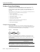
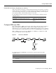
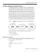
Configure Source-Route Bridging Figure 47 Multiport Bridge Using a Virtual Ring Token Ring T1 Token Ring T2 Ring group T0 Token Ring Token Ring S2324 T3 To take advantage of this virtual ring feature, each Token Ring interface on the router must be configured to belong to the same ring group. For information about configuring a multiport bridge using a virtual ring, see the “Configure a Multiport Bridge Using a Virtual Ring” section later in this chapter.
Configure SRB over FDDI Enable SRB and Assign a Ring Group to an Interface After you have defined a ring group, you must assign that ring group to those interfaces you plan to include in that ring group. An interface can only be assigned to one ring group. To enable any-to-any connectivity among the end stations connected through this multiport bridge, you must assign the same target ring number to all Token Ring interfaces on the router.
Configure Source-Route Bridging Configure Fast-Switching SRB over FDDI Fast-Switching SRB over FDDI enhances performance. For example, if you want to use access-lists, fast-switching SRB over FDDI provides fast performance and access-list filters capability. To configure fast-switching SRB over FDDI, use the following commands, beginning in global configuration mode: Step Command Purpose 1 interface fddi slot/port Configure an FDDI interface.
Enable the Automatic Spanning-Tree Function Forwarding all-routes explorer packets is the default. However, in complicated source-route bridging topologies, using this default can generate an exponentially large number of explorers that are traversing the network. The number of explorer packets becomes quite large because duplicate explorer packets are sent across the network to every node on every path. Eventually each explorer packet will reach the destination device.
Configure Source-Route Bridging To create a bridge group that runs an automatic spanning-tree function compatible with the IBM SRB spanning-tree implementation, use the following command in global configuration mode: Command Purpose bridge bridge-group protocol ibm Create a bridge group that runs the automatic spanning-tree function.
Configure Bridging of Routed Protocols Configure Bridging of Routed Protocols Source-route bridges use Media Access Control (MAC) information, specifically the information contained in the RIF, to bridge packets. A RIF contains a series of ring and bridge numbers that represent the possible paths the source node might use to send packets to the destination. Each ring number in the RIF represents a single Token Ring in the source-route bridged network and is designated by a unique 12-bit ring number.
Configure Bridging of Routed Protocols • • VINES XNS Enable use of the RIF only on Token Ring interfaces on the router. To configure the Cisco IOS software to append RIF information, use the following command in interface configuration mode: Command Purpose multiring {protocol-keyword [all-routes | spanning] | all | other} Enable collection and use of RIF information.
Configure Translation between SRB and Transparent Bridging Environments Configure Translation between SRB and Transparent Bridging Environments Source-route translational bridging (SR/TLB) is a Cisco IOS software feature that allows you to combine SRB and transparent bridging networks without the need to convert all of your existing source-route bridges to source-route transparent (SRT) nodes. As such, it provides a cost-effective connectivity path between Ethernets and Token Rings, for example.
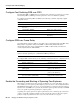
Configure Translation between SRB and Transparent Bridging Environments Figure 50 Example of a Simple SR/TLB Topology Transparent bridging "ring" Source-route bridged domain Router running SR/TLB Transparent bridging domain Token Ring Frames gain RIFs in this direction S1108a Frames lose RIFs in this direction Note The Spanning-Tree Protocol messages used to prevent loops in the transparent bridging domain are not passed between the SRB domain and the transparent bridging domain.
Enable Bridging between Transparent Bridging and SRB We currently know that problems occur with the following protocols when bridged between Token Ring and other media: Novell IPX, DECnet Phase IV, AppleTalk, VINES, XNS, and IP. Further, problems can occur with the Novell IPX and XNS protocols when bridged between FDDI and other media. We recommend that these protocols be routed whenever possible.
Configure Translation between SRB and Transparent Bridging Environments Enable Token Ring LLC2-to-Ethernet Conversion The Cisco IOS software supports the following types of Token Ring-to-Ethernet frame conversions using Logical Link Control, type 2 (LLC2) Protocol: • • Token Ring LLC2 to Ethernet Type II (0x80d5 processing) Token Ring LLC2 to Ethernet 802.3 LLC2 (standard) For most non-IBM hosts, Token Ring LLC2 frames can be translated in a straightforward manner into Ethernet 802.3 LLC2 frames.
Configure NetBIOS Support Configure NetBIOS Support NetBIOS is a nonroutable protocol that was originally designed to transmit messages between stations, typically IBM PCs, on a Token Ring network. NetBIOS allows messages to be exchanged between the stations using a name rather than a station address. Each station knows its name and is responsible for knowing the names of other stations on the network.
Configure NetBIOS Support • • Create Static Entries in the NetBIOS Name Cache Specify Dead-Time Intervals for NetBIOS Packets Enable the Proxy Explorers Feature on the Appropriate Interface In order to enable NetBIOS name caching on an interface, the proxy explorers feature must first be enabled on that interface. This feature must either be enabled for response to all explorer packets or for response to NetBIOS packets only.
Configure the NetBIOS Cache Name Length Configure the NetBIOS Cache Name Length To specify how many characters of the NetBIOS type name that the name cache will validate, enter the following command in global configuration mode: Command Purpose netbios name-cache name-len length Specify the number of characters of the NetBIOS type name to cache. Enable NetBIOS Proxying The Cisco IOS software can act as a proxy and send NetBIOS datagram type frames.
Configure LNM Support The Cisco IOS software also converts pairs of FIND_NAME and NAME_RECOGNIZED packets received from explorers, which traverse all rings, to specific route frames that are sent only between the two machines that need to see these packets. You can specify a query-timeout, or “dead-time” interval to prevent repeat or duplicate broadcast of these type of packets for the duration of the interval.
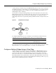
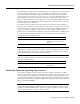
Configure LNM Support Figure 51 LNM Linking to a Source-Route Bridge on Each Local Ring Token Ring PC running LNM SRB B SRB A Token Ring SRB C WAN Token Ring SRB D Token Ring S1113a Token Ring If LNM requires information about a station somewhere on a Token Ring, it uses a proprietary IBM protocol to query to one of the source-route bridges connected to that ring. If the bridge can provide the requested information, it simply responds directly to LNM.
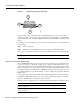
Configure LNM Support Figure 52 LAN Network Manager Monitoring and Translating LAN Network Manager 1 Query about Station A Station A Token Ring Token Ring Proprietary protocol on LLC2 IEEE 802.5 S1114a 2 Query to Station A Notice that the proprietary protocol LNM uses to communicate with the source-route bridge is an LLC2 connection. Although its protocol cannot be routed, LNM can monitor or manage anything within the SRB network. How a Router Works with LNM As of Software Release 9.
Configure LNM Software on the Management Stations to Communicate with the Router When SRB is enabled on the router, configuring the Cisco IOS software to perform the functions of an IBM Bridge for communication with LNM occurs automatically. Therefore, if SRB has been enabled, you do not need to perform any tasks to enable LNM support. However, the LNM software residing on a management station on a Token Ring on the network should be configured to properly communicate with the router.
Configure LNM Support The command can be used to terminate all LNM server input and reporting links. In normal circumstances, this command should not be necessary because it is a superset of the functions normally performed on individual interfaces by the no lnm rem and no lnm rps commands. Disable Automatic Report Path Trace Function Under some circumstances, such as when new hardware has been introduced into the network and is causing problems, the automatic report path trace function can be disabled.
Apply a Password to an LNM Reporting Link To enable other LRMs to change router parameters, use the following command in interface configuration mode: Command Purpose lnm alternate number Enable a LRM other than that connected through link 0 to change router parameters. Apply a Password to an LNM Reporting Link Each reporting link has its own password that is used not only to prevent unauthorized access from an LRM to a bridge but to control access to the different reporting links.
Configure LNM Support Change an LNM Reporting Interval All stations on a Token Ring notify the Ring Error Monitor (REM) when they detect errors on the ring. In order to prevent excessive messages, error reports are not sent immediately, but are accumulated for a short interval and then reported. A station learns the duration of this interval from a router (configured as a source-route bridge) when it first enters the ring. This value is expressed in tens of milliseconds between error messages.
Secure the SRB Network Secure the SRB Network This section describes how to configure three features that are used primarily to provide network security: NetBIOS access filters, administrative filters, and access expressions that can be combined with administrative filters. In addition, these features can be used to increase network performance because they reduce the number of packets that traverse the backbone network.
Secure the SRB Network The NetBIOS station access list contains the station name to match, along with a permit or deny condition. You must assign the name of the access list to a station or set of stations on the network. To assign a station access list name, use the following command in global configuration mode: Command Purpose netbios access-list host name {permit | deny} pattern Assign the name of an access list to a station or set of stations on the network.
Configure Administrative Filters for Token Ring Traffic Command Purpose netbios output-access-filter bytes name Specify a byte-based access filter on outgoing messages. Configure Administrative Filters for Token Ring Traffic Source-route bridges normally filter frames according to the routing information contained in the frame. That is, a bridge will not forward a frame back to its originating network segment or any other network segment that the frame has already traversed.
Secure the SRB Network To enable filtering on input or output, use one of the following commands in interface configuration mode: Command Purpose source-bridge input-lsap-list access-list-number Enable filtering of IEEE 802-encapsulated packets on input by type code. source-bridge output-lsap-list access-list-number Enable filtering of IEEE 802-encapsulated packets on output by type code. You can filter SNAP-encapsulated packets on either input or output.
Configure Access Expressions that Combine Administrative Filters Configure Access Expressions that Combine Administrative Filters You can use access expressions to combine access filters to establish complex conditions under which bridged frames can enter or leave an interface. Using access expressions, you can achieve levels of control on the forwarding of frames that otherwise would be impossible when using only simple access filters.
Secure the SRB Network Configure Access Expressions To configure an access expression perform the following tasks: • • • Design the access expression. Configure the access lists used by the expression. Configure the access expression into the router. When designing an access expression, you must create some phrase that indicates, in its entirety, all the frames that will pass the access expression.
Tune the SRB Network The access lists defined in the previous section create the following configuration: interface tokenring 0 access-expression in ~lsap(202) | dmac(701) ! access-list 202 permit 0x0404 0x0001 ! Permits SNA frames (command or response) access-list 202 permit 0x0004 0x0001 ! Permits SNA Explorers with NULL DSAP ! ! Access list 701 will permit the FEP MAC address ! of 0110.2222.3333 access-list 701 permit 0110.2222.
Tune the SRB Network Enable or Disable the Source-Route Fast-Switching Cache Rather than processing packets at the process level, the fast-switching feature enables the Cisco IOS software to process packets at the interrupt level. Each packet is transferred from the input interface to the output interface without copying the entire packet to main system memory.
Enable or Disable the SSE Enable or Disable the SSE The Silicon Switch Engine (SSE) acts as a programmable cache to speed the switching of packets. To enable or disable the SSE, use one of the following commands in interface configuration mode: Command Purpose source-bridge route-cache sse Enable the SSE function. no source-bridge route-cache sse Disable the SSE function.
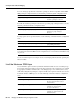
Tune the SRB Network Figure 54 Controlling Explorer Storms in Redundant Network Topologies Station X Token Ring 1 Token Ring 2 Router A Router B Token Ring 3 Station Z S5002 Token Ring 4 The source-bridge explorer-dup-ARE-filter command can be used to reduce explorer traffic by filtering explorer frames.
Configure Proxy Explorers Configure Proxy Explorers You can use the proxy explorers feature to limit the amount of explorer traffic propagating through the source-bridge network. To configure proxy explorers, use the following command in interface configuration mode: Command Purpose source-bridge proxy-explorer Enable the interface to respond to any explorer packets that meet certain conditions necessary for a proxy response to occur.
Monitor and Maintain the SRB Network Report Spurious Frame-Copied Errors An IBM 3174 cluster controller can be configured to report frame-copied errors to IBM LAN Network Manager software. These errors indicate that another host is responding to the MAC address of the 3174 cluster controller. Both the 3174 cluster controller and the IBM LAN Network Manager software can be configured to ignore frame-copied errors.
SRB Configuration Examples Command Purpose show span Display the spanning-tree topology for the router. show sse summary Display a summary of Silicon Switch Processor (SSP) statistics. To maintain the SRB network, use any of the following commands in privileged EXEC mode: Command Purpose clear netbios-cache Clear the entries of all dynamically learned NetBIOS names. clear rif-cache Clear the entire RIF cache. clear source-bridge Clear the SRB statistical counters.
SRB Configuration Examples • • • • • • • • • • NetBIOS Support with a Static NetBIOS Cache Entry Example LNM for a Simple Network Example LNM for a More Complex Network Example NetBIOS Access Filters Example Filtering Bridged Token Ring Packets to IBM Machines Example Administrative Access Filters—Filtering SNAP Frames on Output Example Creating Access Filters Example Access Filters Example Fast-Switching Example Autonomous Switching Example Basic SRB with Spanning-Tree Explorers Example Figure 55 illust
SRB with Automatic Spanning-Tree Function Configuration Example SRB with Automatic Spanning-Tree Function Configuration Example The following example of a Cisco series 7000 router configuration illustrates how to enable the automatic spanning tree function on an SRB network: source-bridge ring-group 100 interface tokenring 0/0 no ip address ring-speed 16 multiring all source-bridge active 1 source-bridge spanning ! interface tokenring 0/1 no ip address ring-speed 16 multiring all source-bridge active 2 sou
SRB Configuration Examples SRB and Routing Certain Protocols Example In the following configuration, IP, XNS, and IPX are routed, while all other protocols are bridged between rings. While not strictly necessary, the Novell IPX and XNS network numbers are set consistently with the IP subnetwork numbers. This makes the network easier to maintain. xns routing 0000.0C00.02C3 ! novell routing 0000.0C00.02C3 ! interface tokenring 0 ip address 131.108.129.2 255.255.255.
SRB with Multiple Virtual Ring Groups Example The following is a sample configuration file: source-bridge ring-group 7 ! interface tokenring 0 source-bridge 1000 1 7 source-bridge spanning ! interface tokenring 1 source-bridge 1001 1 7 source-bridge spanning ! interface tokenring 2 source-bridge 1002 1 7 source-bridge spanning ! interface tokenring 3 source-bridge 1003 1 7 source-bridge spanning SRB with Multiple Virtual Ring Groups Example Two virtual ring groups can only be connected through an actual T
SRB Configuration Examples Configuration for Router B source-bridge ring-group 200 ! interface tokenring 0 source-bridge 3 1 200 source-bridge spanning ! interface tokenring 2 source-bridge 2 1 200 source-bridge spanning SRB over FDDI Configuration Examples The following examples show the configuration for SRB over FDDI as illustrated in Figure 58. Router A dlsw local-peer peer-id 132.11.11.2 dlsw remote-peer 0 tcp 132.11.11.
SRB over Frame Relay Configuration Example SRB over Frame Relay Configuration Example Figure 59 illustrates a network with the following characteristics: • • • • • Virtual Ring Number of Router A = 100 Virtual Ring Number of FRAD B = 200 Virtual Ring Number of FRAD C = 300 DLCI number for PVC between Router A and FRAD B = 30 DLCI number for PVC between Router A and FRAD C = 31 Figure 59 FRAD Using SRB over Frame Relay to Connect to a Cisco Router Token Ring 10 Token Ring 20 Router A FRAD C Token Ri
SRB Configuration Examples Configuration of Router A source-bridge ring-group 100 ! interface Serial1 encapsulation frame-relay ! interface Serial1.1 point-to-point frame-relay interface-dlci 30 ietf source-bridge 200 1 100 conserve-ring source-bridge spanning ! interface Serial1.
Adding a Static RIF Cache Entry for a Two-Hop Path Example Assigning a RIF to a Source-Route Bridge Token Ring 8 Token Ring 9 IBM PC 1000.5A12.3456 Bridge 1 S1100a Figure 60 The static RIF entry would be submitted to the router on the left as follows: rif 1000.5A12.3456 0630.0081.
SRB Configuration Examples Assume that the following configuration for SRB and transparent bridging existed before you wanted to enable SR/TLB: interface tokenring 0 source-bridge 1 1 2 ! interface tokenring 1 source-bridge 2 1 1 ! interface ethernet 0 bridge-group 1 ! interface ethernet 0 bridge-group 1 ! bridge 1 protocol dec To enable SR/TLB, one aspect of this configuration must change immediately—a third ring must be configured.
SR/TLB with Access Filtering Example Once you have determined the ring number and the bridge number, you can add the source-bridge transparent command to the file, including these two values as parameters for the command.
SRB Configuration Examples The command for the Token Ring interface specifies that the access list 701 be applied on the source address of frames going out to the Token Ring, and the command for the Ethernet interface specifies that this access list be applied on the source address frames entering the interface from Ethernet. This would work if both interfaces used the same bit ordering, but Token Rings and Ethernets use opposite (swapped) bit orderings in their addresses in relationship to each other.
LNM for a Simple Network Example LNM for a Simple Network Example Figure 65 shows a router with two Token Rings configured as a local source-route bridge.
SRB Configuration Examples LNM for a More Complex Network Example Figure 66 shows a router with three Token Rings configured as a multiport bridge, thus employing the concept of the virtual ring. Figure 66 Router with Three Token Rings Configured as a Multiport Bridge Physical configuration Token T0 Ring 1 Token T1 Ring 2 T2 Token Ring 3 Logical configuration Token Ring 1 SRB 1 Token Ring 8 SRB 2 Token Ring 3 The associated configuration file follows.
NetBIOS Access Filters Example The show lnm config command displays the logical configuration of this bridge, including all the pertinent information for configuring this router into LNM: Wayfarer# show lnm config Bridge(s) currently configured: From ring 001, address 0000.0028.abcd Across bridge 001 To ring 008, address 4000.0028.abcd From ring 002, address 0000.3000.abc4 Across bridge 002 To ring 008, address 4000.3000.abc4 From ring 003, address 0000.3000.
SRB Configuration Examples Access lists are scanned in order. In the following example, the first list denies all entries beginning with the letters ABC, including one named ABCD. This voids the second command, because the entry permitting a name with ABCD comes after the entry denying it.
Administrative Access Filters—Filtering SNAP Frames on Output Example Administrative Access Filters—Filtering SNAP Frames on Output Example Figure 68 shows a router connecting four Token Rings.
SRB Configuration Examples access-list 203 permit 0xE0E0 0x0101 access-list 203 deny 0x0000 0xFFFF Note that it is not necessary to check for an LSAP of 0xAAAA when filtering SNAP-encapsulated AppleTalk packets, because for source-route bridging, the use of type filters implies SNAP encapsulation.
Access Filters Example Access Filters Example Figure 69 shows two routers connecting two Token Rings to an FDDI backbone. Network Configuration Using NetBIOS Access Filters NetBIOS server FILESVR3 NetBIOS clients Token Ring Router A 3174 Token Ring FDDI 3174 Router B IBM FEP address 0110.2222.3333 S1112a Figure 69 Suppose you want to permit the IBM 3174 cluster controllers to access the FEP at address 0110.2222.3333, and also want the NetBIOS clients to access the NetBIOS server named FILESVR3.
SRB Configuration Examples Autonomous Switching Example The following example enables use of autonomous switching between two ciscoBus Token Ring interfaces in the same router. Frames entering Token Ring interfaces 0 or 1 will be autonomously switched to the other interface.