Ripwave Base Station I&C Guide Navini Networks, Inc. Install the BTS Install Mounting Rack or Enclosure The BTS mounting rack (Figure 17) or enclosure is to be installed in compliance with applicable portions of the National Electrical Code (NEC), articles 800 and 810. You will need to adhere to local installation standards, as well as Navini Networks standards and procedures. Refer to Appendix J for guidelines on outdoor BTS enclosures. Figure 17: BTS Mounting Rack 50 Part #40-00047-00 Rev D v1.
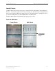
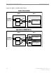
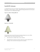
Navini Networks, Inc. Ripwave Base Station I&C Guide Install Chassis The BTS chassis may be one of two types: Combo Chassis or Split Chassis. Prior to Ripwave Release 1.19, only the Combo Chassis was used (Figure 18). The advantage of the Split Chassis has to do with improved RF power output (Figure 19). The Split Chassis is available for the 2.3, 2.5, and 2.6 GHz systems; it is not available for the 2.4 GHz system. Install the BTS chassis in the mounting rack using ten (10) screws.
Ripwave Base Station I&C Guide Navini Networks, Inc. Figure 19: Split Vs.
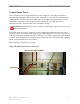
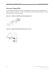
Navini Networks, Inc. Ripwave Base Station I&C Guide Connect Input Power Next, connect the power supply to the BTS card cage (Figure 20). The gauge of the wire is determined by the length of the run and by NEC standards. Use a 60-amp circuit breaker when running the line. Terminate both of the input power wires and the ground wire with a ¼- inch terminal lug. Assuming a +24 VDC power supply, connect the +24 VDC input power connections and the +24 VDC return wires to the BTS card cage.
Ripwave Base Station I&C Guide Navini Networks, Inc. Connect BTS to Ground Connections All connections need to be checked before power is applied to the system. At a minimum, perform the following: • • Ensure continuity across all ground connections. Ensure an open connection from the power supply output (positive input to the BTS card cage) to frame ground.
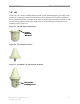
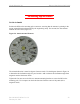
Navini Networks, Inc. Ripwave Base Station I&C Guide Install GPS Antennas As mentioned earlier, there are two models of GPS antennas that can be used with the Ripwave Base Station, as shown in Figures 21 and 22: Motorola Timing 2000 and VIC 100. The system will use either one or two GPS antenna modules. Figure 21: Motorola Timing 2000 GPS Figure 22: VIC 100 GPS The mounting location for the GPS antenna is determined during the site survey.
Ripwave Base Station I&C Guide Navini Networks, Inc. Motorola Timing 2000 For the Motorola Timing 2000, mount each GPS antenna module using the mounting bracket hardware (Figures 23 and 24). Connect the GPS cable(s) to the GPS antenna module(s). Torque the connector(s) to 20-24 inch-pounds. Figure 23: Motorola GPS Antenna Mounting Brackets Figure 24: Motorola GPS Antenna Mounted to a Pole 56 Part #40-00047-00 Rev D v1.
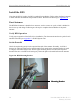
Navini Networks, Inc. Ripwave Base Station I&C Guide VIC 100 For the VIC 100, mount each GPS antenna module, run the cable through the pipe clamp mount (Figure 25). Connect the cable to the GPS antenna, then weatherize the connection (Figure 26). Secure the antenna module to the pipe clamp mount using the captive mounting hardware. Install the GPS antenna module and the pipe clamp mount to the mounting pipe and tighten the two mounting screws (Figure 27).
Ripwave Base Station I&C Guide Navini Networks, Inc. Install the RFS Now that the BTS is in place, the RFS is readied for installation. Follow either the Panel Antenna or Omni Antenna information and procedures below. Reference the drawings in Appendix M. Panel Antenna The RFS Panel antenna is installed on a structure, such as a tower or a pole, which is defined in the site survey and design. Following are the steps to complete the installation of the panel antenna.
Navini Networks, Inc. Ripwave Base Station I&C Guide The following steps are critical ! Set the Azimuth Position the RFS on the mounting pole or structure, ensuring that the antenna is pointing in the proper azimuth direction determined by the engineering study. For an omni, the first antenna element must face East (Figure 29). Figure 29: Omni Antenna Elements The azimuth direction is stated in degrees from true north.
Ripwave Base Station I&C Guide Navini Networks, Inc. Figure 30: Declination Angle Verify the Downtilt Using an inclinometer, check the downtilt of the RFS antenna. If required, adjust the angle using the downtilt adjustment brackets. Be sure to include any electrical uptilt or downtilt built into the antenna in the setting. Tighten the mounting hardware to secure the RFS in the proper position. Recheck the downtilt angle again to verify proper position.
Navini Networks, Inc. Ripwave Base Station I&C Guide Install Surge Protectors The RFS has ten cable connectors on the bottom of the unit. Eight are antenna connections, with the connectors alternately numbered from right to left as shown in Figure 31. The two connectors in the middle are for antenna calibration and data/DC power connections. Install surge protectors on nine (9) of the RFS connectors – the eight antenna connectors and the calibration connector.
Ripwave Base Station I&C Guide Navini Networks, Inc. Figure 32: RFS Connectors 6 2 5 1 RF Cable Connectors Surge Protectors RF Cables Calibration Cable 62 Data/Power Cable Part #40-00047-00 Rev D v1.
Navini Networks, Inc. Ripwave Base Station I&C Guide Figure 33: Completed Cable Installation 8 4 7 3 6 2 5 1 Data/Power Cable Calibration Cable Install Grounding Kit on Cables Install grounding kit wire connections on the eight (8) RFS cables and the one (1) CAL cable per the instruction sheet that comes with the grounding kit. Install the grounding wire in a position on the cable so that it can be attached to the ground buss bar that is mounted close to the RFS.
Ripwave Base Station I&C Guide Navini Networks, Inc. Figure 34: RFS Grounding Ground Wires Ground Buss Bar Earth Ground Test the RFS & Cables Test the RFS and the eight (8) cables per Appendix C, the RFS System Test. Record the results in the form. For this test, use the cable connectors that will be attached to the BTS. Include the jumpers and all surge protectors.
Navini Networks, Inc. Ripwave Base Station I&C Guide Connect RF Cables & Alarms to BTS Connect all of the cables to the BTS. The connection points are shown in Figures 36, 37, and 38. Torque the cable connectors to 20-24 inch-pounds. If applicable, connect the cabinet alarm connector and Battery Backup connector (Cabinet Alarm and BBU) to the back of the chassis. More information on connecting alarms, rectifiers, and battery backup equipment are provided in Appendix L and Appendix N, respectively.
Ripwave Base Station I&C Guide Navini Networks, Inc. Figure 37: Split Chassis RF/PA Shelf Rear View Figure 38: Split Chassis Digital Shelf Rear View Power Connectors ON/OFF Battery Backup Connector Cabinet Alarms Connector GPS 1 GPS 2 Data/Power Cable Connector Cal Cable 66 Part #40-00047-00 Rev D v1.
Navini Networks, Inc. Ripwave Base Station I&C Guide Omni Antenna The RFS Omni antenna is installed on a structure, such as a tower or a pole, which is defined in the site survey and design. Following are the steps to complete the installation of the panel antenna. Assemble the Antenna Mount per the instructions that come with it (Figure 39). Use a compass to determine which direction is true East (incorporating declination angle - see Figure 30).
Ripwave Base Station I&C Guide Navini Networks, Inc. Sweep the RFS antenna inputs for db loss. Record all results for later calculations. Position the RFS on the Antenna Mount, ensuring that the arrow on the bottom of the Antenna Mount faces true East. Secure the RFS antenna to the Antenna Mount (Figure 41). Install surge protectors on the 8 antenna and 1 cal connectors. Figure 41: Omni Ground Stud Ground stud Connect the eight antenna cables, cal cable, and Data/Power cable to the RFS antenna.
Navini Networks, Inc. Ripwave Base Station I&C Guide Verify Installed Circuit Cards WARNING! Ensure that power to the BTS chassis is off before installing the circuit cards or any of the RF Power Amplifiers in the chassis. The circuit cards, including the RF/PA cards, normally come seated in the BTS chassis. If they are already installed, verify that the correct cards are placed and seated properly. The RF/PA modules may be installed in any position on the top (RF) shelf.
Ripwave Base Station I&C Guide Navini Networks, Inc. Table 9: Digital Card Names Abbreviation SYN IF CHP MDM CC Card Name Synthesizer Intermediate Frequency Channel Processor Modem Communications Controller Number of Cards 1 or 2 Always 2 Always 2 Always 2 1 or 2 Base Station Installation Certification When the installation of the equipment is complete, the Base Station Installation Certification form needs to be completed and signed off by both the installer and the customer.
Navini Networks, Inc. Ripwave Base Station I&C Guide Chapter 3: Commissioning This chapter provides post-installation instructions on provisioning, configuring, calibrating, testing, and commissioning the Ripwave Base Station. Review Customer Network Plans As part of preparing to put the BTS into commission, it is important to review the actual installed site against the customer Network Architecture Plan - i.e., checking that all equipment and software are installed and available for use.
Ripwave Base Station I&C Guide Navini Networks, Inc. Figure 44: Ports on CC Card Ethernet Connector Serial Port Connector (aka, Console Port) T1 Connectors If the customer’s EMS is installed and can be accessed through the backhaul, it can be connected via T1 or Ethernet to the BTS and used for testing purposes. The EMS software installation procedures can be found in the EMS Software Installation Guide, P/N 40-00017-00.
Navini Networks, Inc. Ripwave Base Station I&C Guide Configure & Power Up the BTS Overview During initial power up a minimal set of configuration parameters have to be input to the BTS through the serial port on the CC card. These early configuration parameters are referred to as the “boot parameters”. They are required to get the BTS to communicate with the EMS Server so that all the configuration data can be downloaded from EMS to the BTS. The PC used at this point is a Test EMS Server (i.e., laptop).
Ripwave Base Station I&C Guide Navini Networks, Inc. Figure 45: COM1 Properties Bits per second: 9600 Data Bits: 8 Parity: None Stop Bits: 1 Flow Control: None Step 7. On the Test EMS Server, click on the Server icon to start the EMS Server. NOTE: This step assumes you have loaded and configured the EMS Server & Client applications. Step 8. Click on the EMS Configuration & Alarm Manager (CAM) icon to start the EMS Client GUI. Step 9.
Navini Networks, Inc. Ripwave Base Station I&C Guide Configure RFS (Splitter Loss Value) Each RFS shipped is pre-programmed for the customer’s specific operating environment. An RFS Configuration CD accompanies the RFS equipment when it is shipped. The CD includes an RFS script and a Quick Guide with procedures on selecting the appropriate splitter loss values to be entered into the EMS database for the given Base Station. Each Configuration disk is unique to the individual RFS that is shipped.
Ripwave Base Station I&C Guide Navini Networks, Inc. Step 7. Save this file as text, and then close it. Step 8. Start the EMS Config CLI application to run “script ”. Do this by entering the following: >enable >configure >script scripts/rfs/rfs__<7-digit frequency>.cli NOTE: For Unix operating systems, the CLI text is case sensitive and the slash marks should be backward slashes instead of forward slashes. Step 9.
Navini Networks, Inc. Ripwave Base Station I&C Guide Figure 46: BTS Power On Switches Combo Chassis Power ON/OFF Split Chassis Off/On switch Step 3. Watch for the auto-boot countdown command. Type in config on the computer keyboard to interrupt the standard boot sequence. The window of time to type in “config” after auto-boot starts is 20 seconds. BTS Bootup The BTS is shipped with a default value of a 20-second countdown to interrupt the standard bootup sequence.
Ripwave Base Station I&C Guide Navini Networks, Inc. Boot Prompt After you have escaped from the automated boot sequence, the console will display a rudimentary Boot prompt: [Navini Boot]: This prompt offers the ability to perform a small set of operations. Enter ‘?’ or ‘h’ followed by the Enter key to display a list of commands (Exhibit 1). To invoke any of the commands, simply enter the single letter command with optional parameters, followed by the Enter key. .
Navini Networks, Inc. Ripwave Base Station I&C Guide f – Fill memory allows you to alter portions of the BTS’s memory with a fixed pattern. It should only be performed with the assistance of a certified Navini service technician. t – Fill memory allows you to alter portions of the BTS’s memory with a pattern from another area of memory. It should only be performed with the assistance of a certified Navini service technician.
Ripwave Base Station I&C Guide Navini Networks, Inc. EMS This section concerns the configuration of the EMS Server itself. First, the Internet (inet) IP address of the Server is specified. Make sure to fill this field with the address of the Server used to configure this BTS. Your BTS is shipped with this field un-initialized. You must provide a valid 4-digit IP address before you can proceed. For example: ems inet : 172.16.0.
Navini Networks, Inc. Ripwave Base Station I&C Guide For this reason, the BTS only allows you to enter odd addresses in the range XXX.XXX.XXX.1 to XXX.XXX.XXX.253 in this field. The standby field is only displayed for your convenience and cannot be altered. Note that the BTS automatically handles switching the address when a failure occurs on an active Controller card, requiring the standby Controller to go into service. However, the MAC addresses remain fixed.
Ripwave Base Station I&C Guide Navini Networks, Inc. ATM/T1 Configuration For an ATM/T1 configuration, the items shown in Exhibit 3 are identical to Ethernet with the exception of the traffic path, which must show “atm” for this type of configuration. Exhibit 3: ATM/T1 Configuration date and time : 01/09/2003[10:22] autoboot countdown : delayed ems inet : 172.16.0.10 snmp community : public traffic path : atm mac address : 00:04:6a:00:01:20 ip on atm (active) : 172.16.23.181 ip on atm (standby) : 172.16.
Navini Networks, Inc. Ripwave Base Station I&C Guide The PVC configuration is broken into 3 sections: ATM layer parameters; optional Inverse Multiplexing over ATM (IMA) parameters, and T1 physical layer parameters. The first item selects which ATM interface will be used for the Management PVC. If IMA is not selected, you may select from one of the 8 T1 ports numbered 1-8 using the option t1-N, where N is the port number. This is the same interface port number specified in the EMS.
Ripwave Base Station I&C Guide Navini Networks, Inc. The final set of values is used to configure the T1 parameters. The line type allows you to select Extended Super-Frame (ESF) or D4. ESF format is the standard format for ATM/T1 applications. D4 format is supported as an alternate; however, T1 signaling capabilities may be limited. Check your network plans for a definition for your specific application.
Navini Networks, Inc. Ripwave Base Station I&C Guide Each group identifies a set of T1 ports that are being combined to form one larger virtual port. For the sake of boot parameter specification, ALL T1 interfaces for the Management PVC’s IMA group are assumed to be identical. So the parameters for T1 specifications apply to all T1’s of the IMA group: pvc type-atm i/f : ima-0 Once the IMA interface is selected, a set of IMA parameters must be specified for the IMA group used by the Management PVC.
Ripwave Base Station I&C Guide Navini Networks, Inc. Exhibit 6: IMA Clock Mode ima clock mode pvc id size vpi:vci pvc vpi:vci pvc service category pvc atc pcr:cdvt line type line coding line length (ft) line clock source : : : : : : : : : ctc [ctc|itc] 3:10 1:100 ubr 3641:100 esf b8zs 500 loop Standard Boot Sequence The first items in Exhibit 7 (Ethernet) and Exhibit 8 (ATM) illustrate the BOOTROM loading and launching of the core application.
Navini Networks, Inc. Ripwave Base Station I&C Guide Starting CDI..............................Done Starting CAM I/f..........................Done Starting MME..............................Done Starting EtherBridge......................Done Starting DHCP Relay Agent.................Done Starting Peer ARP Proxy Agent.............Done Starting Host ARP Proxy Agent.............Done Starting Mobile IP Proxy Agent............Done Starting LLC Proxy........................
Ripwave Base Station I&C Guide Navini Networks, Inc. KERNEL : 5.4(WIND version 2.5) BSP : 1.0/01.19.00.00 CPU: CC (PPC860P). Processor #0. Memory Size: 0x3f80000. WDB: Ready. Last reset caused by a power on condition. Current time is FRI JUL 12 14:48:29 2002 bts-4 [Active]% Exhibit 8: Standard ATM Boot Sequence - Example System Boot Copyright 2000-2001 Copyright 1984-1998 Navini Networks, Inc. Wind River Systems, Inc. CPU: CC (PPC860P) Kernel Version: 5.4 BSP version: 1.
Navini Networks, Inc. Ripwave Base Station I&C Guide Configuring IMA Group.....................Done Configuring IMA Link......................Done Configuring PVC(s)........................Done Configuring Management PVC................Done Initializing SNMP Agent ..................Done Pinging EMS (172.28.79.30)................Done Loading MTMG..............................Done Loading MDSW..............................Done Loading MBSW..............................Done Loading CAP.......................
Ripwave Base Station I&C Guide Navini Networks, Inc. Last reset caused by a power on condition. Current time is FRI JUL 12 14:26:59 2002 bts-4 [Active]% Attaching to TFFS... done. Loading /tffs0/LOADS/BTSB/core... 4337576 Starting at 0x10000... Auto-booting..............................Done The line items in Exhibit 9 are the ones that create and initialize the core components to the BTS’s on-board file system. This file system is used to store operating code images, configuration data, and log files.
Navini Networks, Inc. Ripwave Base Station I&C Guide Next, the user interface through the console port on the BTS is activated. It should be noted however, that once the Telnet Daemon has been started, this same interface is available remotely through a password protected telnet session. You can access the remote shell service by telnetting directly to the well-known Telnet port (23) of the BTS: Starting Telnet Daemon....................
Ripwave Base Station I&C Guide Navini Networks, Inc. A Command and Debug Interface is initialized to extend rudimentary target shell capabilities for Navini developers to diagnose problems with the Digital Signal Processors on the MDM and CHP cards: Starting CDI..............................Done The Content Addressable Memory (CAM) is used to provide mappings of users to channels. This mapping interface is started at this point: Starting CAM I/f..........................
Navini Networks, Inc. Ripwave Base Station I&C Guide The next item that appears notifies the user of the location where the BTS is retrieving its Management Information Base (MIB). After initial installation and provisioning through the boot line, “EMS” is selected as the Config Data Source. In this case, all remaining parameters are downloaded from the EMS.
Ripwave Base Station I&C Guide Navini Networks, Inc. The BTS is now provisioned with minimal data. This is enough data to be able to calibrate and test the BTS. Power cycle the BTS for the changes to take place. An example of a reboot is shown in Exhibit 11. Exhibit 11: BTS Reboot - Example !!!!! Shutdown Started. Terminating all interfaces!!!!!! Stopping Ime..............................Done Stopping Cme..............................Done Stopping EtherBridge......................Done Stopping CAM I/f....
Navini Networks, Inc. Ripwave Base Station I&C Guide Loading CAP...............................Done Loading BAUX..............................Done Loading BMCB..............................Done Loading MACA..............................Done Loading MACB..............................Done Loading CHAD..............................Done Loading CHTT..............................Done Loading CDSW..............................Done Loading BDSC..............................Done Loading CHSL......................
Ripwave Base Station I&C Guide Navini Networks, Inc. Calibrate the Base Station Calibrating the Base Station detects the phase differential between the antennas and matches the output power across all antennas in the RFS. The calibration procedure must be performed at least three times to ensure validity. Ensure that the BTS has been powered on with the power amplifiers on for at least fifteen minutes to allow them time to warm up and stabilize.
Navini Networks, Inc. Ripwave Base Station I&C Guide Figure 48: Calibrate BTS Step 7. When the Warning window appears (Figure 49), click Yes. Figure 49: Warning Window Part #40-00047-00 Rev D v1.
Ripwave Base Station I&C Guide Step 8. Navini Networks, Inc. The Full Calibration window appears during system calibration (Figure 50). When calibration is complete, the Full Calibration window changes and displays the finish time and the result. Click the Close button to close the Full Calibration window. Note that the result of “Done” does not mean that the system passed calibration. Figure 50: Full Calibration Window Step 9. Click Show Configuration and select the Antenna Table tab (Figure 51).
Navini Networks, Inc. Ripwave Base Station I&C Guide Step 10. Perform the calibration function two more times. Ensure each time that the values remain relatively stable (+/- 3), and that none of the results is zero. After you perform the second calibration, click on Configure. The Config Layer 1 Data window (Figure 52) shows the data from the second calibration. The values in the main screen from the Show Config selection are from the first calibration.
Ripwave Base Station I&C Guide Navini Networks, Inc. Verify the Calibration Base Station Calibration Verification is a set of procedures to verify that the equipment has passed calibration and that the RF portion of the equipment is operating within acceptable parameters. The results of the tests should be documented in the Base Station Calibration Verification Form, P/N 40-00059-00. This form, along with instructions, may be found in Appendix F.
Navini Networks, Inc. Ripwave Base Station I&C Guide Figure 53: Reference Cable Measurement Spectrum Analyzer Signal Generator Reference Cable Figure 54: Reference & Test Cable Measurements Spectrum Analyzer Reference Cable Part #40-00047-00 Rev D v1.
Ripwave Base Station I&C Guide Navini Networks, Inc. Figure 55: Coupler Measurement Spectrum Analyzer Signal Generator Coupler Reference Cable Test Cable Test Procedure Step 1. Connect a test cable to the Signal Generator and to the Spectrum Analyzer. This will be the reference cable (Figure 53). Step 2. Turn on RF Power on the Signal Generator. Step 3.
Navini Networks, Inc. Ripwave Base Station I&C Guide Receive Verification This test verifies the Receive function of the Base Station. Equipment Required • • • • Signal Generator - Agilent 8648C, or equivalent, tunable to the RFS center frequency Oscilloscope – Agilent 54622 D, or equivalent Test cable (optional) Test Channel Processor board Note: Some test equipment may have a DC block for input protection. If so, do not remove the DC block from the equipment.
Ripwave Base Station I&C Guide Navini Networks, Inc. Test Procedure Follow the steps in the procedure below. Step 1. Ensure that system calibration has been successfully performed. Step 2. Enter the value for receive sensitivity (line 23) into the Base Station Calibration Verification Form. It is located in the EMS Configuration & Alarm Manager (CAM) GUI by selecting the BTS, then selecting air interface > layer 1 > show configuration. Select the General tab. Step 3.
Navini Networks, Inc. Ripwave Base Station I&C Guide Figure 56: Test Equipment for Receive Verification Signal Generator RFS Calibration cable Test Cable (optional) 8 RF cables from the RFS connected to the BTS Oscilloscope To test points on CHP card Channel 1 Ext. Trigger on the rear of the scope, If available. Or use Channel 2 input and select it as the trigger source. To the TDD SYNC connector on the back of the BTS (if enabled) Test Points on CHP Test Board D B C A BTS Step 13.
Ripwave Base Station I&C Guide Navini Networks, Inc. Figure 57: Oscilloscope Receive Time Step 14. Measure the RMS voltage (in mV) in the quietest area of each of the four baseband signals from the front of the Channel Processor test board – test points A, B, C, D. Enter the values into the Base Station Calibration Verification Form under receiver performance - noise level (lines 76 to 79).
Navini Networks, Inc. Ripwave Base Station I&C Guide Step 24. After the BTS boots up, repeat steps 12 thru 17 for the CHP test board in the CHP-B slot. Enter the data into the Base Station Calibration Verification Form (lines 80 to 83). Step 25. Turn off the Oscilloscope. Step 26. Set the power switch on the BTS to OFF. Step 27. Remove the CHP test board from the BTS chassis. Step 28. Install the CHP-B board into the BTS chassis. Step 29. Set the power switch on the BTS to “ON”. Step 30.
Ripwave Base Station I&C Guide Navini Networks, Inc. * If the Spectrum Analyzer will not support 5 MHz RBW, use the following formula to determine the correction factor: 10 * log10 (5 MHz /RBW). Add this value to the measurements. **If possible, connect a cable from the TDD SYNC connector on the back of the BTS to the EXT TRIGGER input on the rear of the Spectrum Analyzer. Set the TRIG to EXT. ***If the RMS detector is not available, measure with the peak detector and subtract 9.
Navini Networks, Inc. Ripwave Base Station I&C Guide Figure 58: Test Equipment for Transmitter Verification RFS All cables from the RFS are connected to the BTS except for the channel being tested Connect the Coupler input directly to the BTS antenna output to be measured Coupler (20dB min) Attenuator 30dB 5W 50 ohm 25W Terminator Coupled port Connect the TDD Sync connector on the back of the BTS to the External Trigger input on the Spectrum Analyzer BTS Spectrum Analyzer Step 4.
Ripwave Base Station I&C Guide Navini Networks, Inc. Figure 59: Sync Signal Display Line Step 6. Repeat steps 1 through 5 for the remaining seven antenna outputs. Record the peak value into the spreadsheet under analyzer readings – Peak (lines 90 to 97). Step 7. Enter the value for antenna power that is set in the EMS into the spreadsheet (line 30). It is located in the EMS Configuration & Alarm Manager GUI by selecting the BTS, then selecting air interface > layer 1 > show configuration.
Navini Networks, Inc. Ripwave Base Station I&C Guide Perform Local CPE Tests Local wireline, then over-the-air, CPE testing will verify that the Base Station is working and is able transmit and receive data. Data rates are not being checked at this time. Refer to Figure 60 when setting up and performing the Wired CPE procedures. Wired CPE Test Equipment Required • • • • CPE - Ordinate the Ripwave Modem (CPE) PC - Laptop with CPE debug tool.
Ripwave Base Station I&C Guide Navini Networks, Inc. Equipment Settings Part of the Test Procedures below. Test Procedure Setup Set up the test procedures, per the following. Step 1. Calibrate and sanity check the BTS. Step 2. Connect the CPE and the attenuators. The combined attenuation should be set roughly as follows: Total attenuation = PTX - 30 + 18 - Cal cable loss + 80 Where PTX is the Tx output power at antenna input port that is set in EMS during calibration.
Navini Networks, Inc. Step 7. Ripwave Base Station I&C Guide Calculate the maximum path allowed as follows: Max loss = Attenuation total + Cal cable loss + 30 Where Attenuation total is the total attenuation of all attenuators (fixed + adjustable). Test Procedure - Check BTS Sensitivity (Individual Antenna) Step 1. Set the attenuation of the attenuator so the total attenuation is about PTX - 30 - Cal cable loss +80. Step 2. Activate antenna #1 only. Step 3.
Ripwave Base Station I&C Guide Navini Networks, Inc. Step 4. Calculate the effective noise floor: NF= SNRTCC - LevelTCC. Where SNRTCC is the TCC SNR and LevelTCC is the received uplink TCC level. NF should be close to SNR - BTS Sensitivity +25 ±5. Where BTS sensitivity is the BTS sensitivity setting during calibration. Step 5. Record the CPE output power. Step 6. Increase the attenuation by 10dB (increase the attenuation of the adjustable attenuator). Step 7.
Navini Networks, Inc. Ripwave Base Station I&C Guide Over-the-air CPE Test Equipment Required Same as for Wired CPE Test. Equipment Settings Included in the Test Procedure. Test Procedure To set up a CPE for local over-the-air testing, follow the steps below. Step 1. Connect a CPE to a test computer. Reference the Ripwave CPE User Guide, P/N 4000026-00 for CPE setup procedures. The location of the test computer setup needs to be close to the Base Station, within its coverage range. Step 2.
Ripwave Base Station I&C Guide Navini Networks, Inc. Install & Test Customer EMS Operations If you have been using a Test EMS up to this point, you will now need to install and test the customer’s EMS server. This involves installing the EMS Server and Client on a computer that is connected through the system backhaul. If the customer’s EMS is already installed and has been used for testing purposes, skip to the “Verify System Performance” section of this chapter.
Navini Networks, Inc. Ripwave Base Station I&C Guide Verify System Performance Drive Study The preliminary Drive Study is performed if no RF coverage model is available. The Drive Study helps you to map out the coverage area. Later, the full Drive Study is performed to see if the system’s coverage area is as predicted and, if necessary, to fine-tune the RF model.
Ripwave Base Station I&C Guide Navini Networks, Inc. 8. Conduct full NLOS Location Tests. 9. Send all test results to Navini’s Technical Support for evaluation. The cycle continues until the performance objectives are reached. Verify System Operation With Multiple CPE’s Set up three computers with CPE’s connected to them. Perform file transfers from all three computers to verify Base Station operation.
Navini Networks, Inc. Ripwave Base Station I&C Guide Appendix A: Ordering Documentation & Forms Navini Networks product documentation and forms may be ordered by calling 1-972-852-4200, or by using the web site: www.navini.com. Select Support / Technical Support.
Ripwave Base Station I&C Guide Ripwave Modem User Guide EMS Administration Guide Ripwave Configuration Guide EMS CLI Reference Manual EMS Alarm Resolution Reference Manual EMS Diagnostic Tools User Guide 120 Navini Networks, Inc. 40-00111-00/40-00097-00 English /40-00099-00 Spanish 40-00031-00 40-00016-01 40-00016-02 40-00033-00 40-00032-00 Part #40-00047-00 Rev D v1.
Navini Networks, Inc. Ripwave Base Station I&C Guide Appendix B: Site Candidate Evaluation Form NAVINI NETWORKS SITE EVALUATION FORM PN - 40-00091-00 Site Name Date FSE SITE INFORMATION COMPANY NAME ADDRESS SITE OWNER SITE CONTACT NO. GPS COORDINATES ANT TYPE (OMNI, PANEL) LAT OMNI PANEL ENCLOSURE TYPE (HUT, ETC) 2.4GHZ ELEV (AMSL) TOWER TYPE (SS, MP,ETC) SITE ACCESS RESTRICTIONS LONG 2.3GHZ HEIGHT (AGL) 24HRS 2.5GHZ 2.
Ripwave Base Station I&C Guide Navini Networks, Inc.
Navini Networks, Inc. Ripwave Base Station I&C Guide NAVINI NETWORKS SITE EVALUATION FORM Site Name 0 SITE MAP / SKETCH Comments GPS ANTENNA LOCATION Comments Part #40-00047-00 Rev D v1.
Ripwave Base Station I&C Guide Navini Networks, Inc. NAVINI NETWORKS SITE EVALUATION FORM Site Name 0 NORTH VIEW Comments NORTHEAST VIEW Comments 124 Part #40-00047-00 Rev D v1.
Navini Networks, Inc. Ripwave Base Station I&C Guide NAVINI NETWORKS SITE EVALUATION FORM Site Name 0 EAST VIEW Comments SOUTHEAST VIEW Comments Part #40-00047-00 Rev D v1.
Ripwave Base Station I&C Guide Navini Networks, Inc. NAVINI NETWORKS SITE EVALUATION FORM Site Name 0 SOUTH VIEW Comments SOUTHWEST VIEW Comments 126 Part #40-00047-00 Rev D v1.
Navini Networks, Inc. Ripwave Base Station I&C Guide NAVINI NETWORKS SITE EVALUATION FORM Site Name 0 WEST VIEW Comments NORTHWEST VIEW Comments Part #40-00047-00 Rev D v1.
Ripwave Base Station I&C Guide Navini Networks, Inc. NAVINI NETWORKS SITE EVALUATION FORM Site Name 0 EXISTING COMPOUND PICTURE Comments GROUNDING Comments 128 Part #40-00047-00 Rev D v1.
Navini Networks, Inc. Ripwave Base Station I&C Guide NAVINI NETWORKS SITE EVALUATION FORM Site Name 0 INGRESS Comments EGRESS Comments Part #40-00047-00 Rev D v1.
Ripwave Base Station I&C Guide Navini Networks, Inc. NAVINI NETWORKS SITE EVALUATION FORM Site Name 0 POWER Comments TELCO Comments 130 Part #40-00047-00 Rev D v1.
Navini Networks, Inc. Ripwave Base Station I&C Guide NAVINI NETWORKS SITE EVALUATION FORM Site Name 0 SHELTER PICTURE Comments SHELTER LAYOUT AND DIMENSION DRAWING Comments Part #40-00047-00 Rev D v1.
Ripwave Base Station I&C Guide 132 Navini Networks, Inc. Part #40-00047-00 Rev D v1.
Navini Networks, Inc. Ripwave Base Station I&C Guide Appendix C: RFS System Test (Cable Sweeps) Introduction Before installing a Base Station at a site, the RFS and the associated cables must be tested, and the results of the tests documented. The tests verify the performance of three major components: the data/power cable, the RF cables, and the RFS unit. This procedure includes, as well, the full RFS sub-assembly with the associated cables.
Ripwave Base Station I&C Guide Navini Networks, Inc. Table C1: Pinout Details Circular Connector(s) A B C D E F G H J K L M POWER CABLE PIN OUT W ire Color Wire Color Signal Name RED BLACK BROWN DRAIN BLACK W HITE BLUE BLACK BLACK GREEN BLACK YELLOW +12V A +12V A RTN Heater GND (Shield Wire) RX_EN_BRX_EN_B+ RX_EN_A+ RX_EN_ADiagbusDiagbus+ +12V B Return +12V B PAIR PAIR PAIR PAIR PAIR Perform the continuity test with both the Volt Ohm Meter (VOM) and the power/data cable tester.
Navini Networks, Inc. Ripwave Base Station I&C Guide Continuity Test With Power/Data Cable Tester Step 1. Connect one end of the power/data cable to the connector on the power/data cable tester. Step 2. Using a VOM/DVM set to ohms, check resistance to ground on the other end of the cable. Resistance is checked from the case of the connector to the individual pin. Resistance readings (+/- 10 percent ) are shown in Table C2. Table C2: Resistance to Ground Pin A B E F Resistance 1K ohms 2K ohms 3.
Ripwave Base Station I&C Guide Navini Networks, Inc. Table C4: Active & Passive RFS Loss / Operating Parameters PA Max Output Power [dBm] 2.3 +38 BTS Max Output power with *Filter [dBm] +37 CAL Cable Min Loss CAL Cable Max Loss RF Cable Min Loss [dB] Active RFS Loss Typ [dB] Passive RFS Loss Typ [dB] TX Pwr to Ant Max [dBm] RX Power to Ant Min [dBm] RX Power to Ant Max [dBm] 1.7 TX Pwr to Ant Min [dBm] 20 3.0 6.0 0 3.2 35 -95 -75 2.4 +37 N/A 4.0 9.5 0 3.2 1.
Navini Networks, Inc. Ripwave Base Station I&C Guide Test Setup When performing each type of sweep, the sweep has to be performed at certain frequency intervals (Table C5). Perform the complete test at the first frequency. Go to the next frequency and recalibrate the test setup. Perform the complete test again. Do the same for the third frequency. Refer to Figure C2. Table C5: Sweep Frequencies System 2.3 GHz High band 2.3 GHz Low band 2.4 GHz 2.5 GHz 2.6 GHz 2.
Ripwave Base Station I&C Guide Navini Networks, Inc. Test Procedure The following procedures are for the Agilent E4402B Spectrum Analyzer. If alternative equipment is used, refer to the manufacturer’s calibration procedures. The key point is to make accurate microwave frequency power measurements. Step 1. Turn the Signal Generator and Spectrum Analyzer on. Allow the equipment to warm up for 15 minutes for the output to stabilize. Step 2.
Navini Networks, Inc. Ripwave Base Station I&C Guide RF Cable Insertion Loss This test is performed on all RF cables that are installed in the system. This includes the eight antenna cables, the system calibration cable, and all jumper cables. Follow the procedures for either the cables on the ground or cables run up the tower. Test Procedure For RF Cables on the Ground Step 1. Ensure calibration of the test setup has been performed each time the test frequency is changed. Step 2.
Ripwave Base Station I&C Guide Step 6. Navini Networks, Inc. The result should be within +/- 0.5 dB of the calculated value. If the insertion loss results do not agree with the manufacturer’s data, check the connectors for proper connection to the cable, and check for kinks in the cable. If the Spectrum Analyzer has a distance to fault (DTF) function, it can be used to help troubleshoot kinks in the cable. CAUTION! Cables with results greater than the specified limits (i.e.
Navini Networks, Inc. Ripwave Base Station I&C Guide Figure C5: Insertion Loss (Cables on Tower) Marker Measurement Example Step 8. The result should be within +/- 0.5 dB of the calculated value. If the insertion loss results do not agree with the manufacturer’s data, check the cable connectors for proper connection to the cable, and check for kinks in the cable. If the Spectrum Analyzer has a distance to fault (DTF) function, this can be used to help troubleshoot kinks in the cable. Step 9.
Ripwave Base Station I&C Guide Navini Networks, Inc. RFS Test Box Setup Step 1. For RFS only testing, connect the power/data test cable to the data connector on the RFS and to the RFS Test Box. OR For RFS and cable testing, connect the installation power/data cable to the data connector on the RFS and to the RFS Test Box. Refer to Figure C6. Step 2. Connect the RFS Test Box power supply to the RFS Test Box. Step 3. Plug the RFS Test Box power supply into a 110 VAC outlet.
Navini Networks, Inc. Ripwave Base Station I&C Guide Figure C7: RFS Only Tx Verification Barrel connector Signal Generator cable to RFS antenna 1 connector Spectrum Analyzer cable to RFS cal connector Note: The position of the RFS will vary the sweep results due to reflections from the test surface. Step 4. Take a marker measurement on the Spectrum Analyzer by using the ‘marker to peak’ or the ‘peak search’ function. The screen on the Spectrum Analyzer should look similar to the one shown in Figure C8.
Ripwave Base Station I&C Guide Step 5. Navini Networks, Inc. The marker value should be equal to the RFS Only Tx insertion loss within +/- 2.0 dB, per the manufacturer’s data. If the insertion loss results do not agree with the manufacturer’s data, check the test setup. Caution: An RFS with results greater than the +/- 2.0 dB limits should not be installed, as a potential hardware fault exists. Contact Navini Networks Technical Support. Step 6.
Navini Networks, Inc. Ripwave Base Station I&C Guide Note: The position of the RFS will vary the sweep results due to reflections from the test surface. Step 5. Take a marker measurement on the Spectrum Analyzer by using the ‘marker to peak’ or the ‘peak search’ function. The screen on the Spectrum Analyzer should look similar to the one shown in Figure C10. Figure C10: RFS Only Rx Marker Measurement Example Step 6. The marker value should be equal to the RFS Only Rx insertion loss within +/- 2.
Ripwave Base Station I&C Guide Navini Networks, Inc. RFS & Cables Transmit Verification This test is performed after the RFS is installed and the antenna cables, calibration cable, and power/data cable are connected to the inputs on the RFS. Step 1. Step 2. Step 3. Step 4. Step 5. Ensure calibration of the test setup and RFS Test Box setup for RFS and cables has been performed each time the test frequency is changed. Switch the RFS Test Box to the Transmit (Tx) mode.
Navini Networks, Inc. Ripwave Base Station I&C Guide Caution: If RFS & cables test results are greater than the +/- 2.0 dB limits, they should not be installed on a tower, as a potential hardware fault exists. Verify the connections and contact Navini Networks Technical Support. Step 7. Step 8. Step 9. Record the data in the RFS System Test Form under “TOTAL TX PATH LOSS (CABLE-RFS)”. Ensure that the information is recorded under the channel number that is on the cable label.
Ripwave Base Station I&C Guide Step 7. Navini Networks, Inc. The marker value should be equal to the RFS Only RX Insertion Loss + Calibration Cable Loss + Antenna Cable Loss + Antenna Cable Jumper Loss. RX Insertion Loss should be within +/- 2.0 dB of the sum of the parts. If the Insertion Loss results do not agree with the manufacturers data, check the test setup and the cable connections. Caution: If RFS & cables test results are greater than the +/- 2.
Navini Networks, Inc. Ripwave Base Station I&C Guide 2.4 RFS System Test Form 2.
Ripwave Base Station I&C Guide Navini Networks, Inc. 2.6 RFS System Test Form 2.
Navini Networks, Inc.
Ripwave Base Station I&C Guide Grounding F 1 2 3 4 5 6 7 8 9 10 11 12 13 14 15 16 17 18 Monopole/Tower Grounding Installed Ground Wire Types and Size meet construction Specs Lightning Rod Provided and Installed Per Plan 5 Ohm Megger Ground Resistance Test Complete Buss Bars Installed Per Plan Surge Protector Installed Between RFS Antenna and Cable Coax Ground Kits Installed at RFS Antenna Per Plan Coax Ground Kits Installed at Tower Base Per Plan Coax Ground Kits Installed at Buss Bar Prior to BTS Per Pl
Navini Networks, Inc.
Ripwave Base Station I&C Guide Navini Networks, Inc. Appendix E: Configuration Forms The configuration forms are used to plan and design the operating parameters for the system. The parameters for every system element are defined in the EMS Server.
Navini Networks, Inc. Ripwave Base Station I&C Guide IP Field Name Values BTS IP Address EMS Server IP Address BTS Default Gateway BTS Subnet Mask Street Address City State Zip BTS ID BTS Name Suppress Alarms TRUE or FALSE Suppress CPE Registration TRUE or FALSE Calibration Interval (hours) Bridge Aging Timer (minutes) 1 - 24 Enable PVC Loopback TRUE or FALSE 1 - 60 BTS Contact Personnel BTS Configuration Source EMS or BTS Interface Type BTS Profile Type Ethernet or ATM Unlicensed 2.
Ripwave Base Station I&C Guide Navini Networks, Inc. 2.602 - 2.686 GHz Filter component of the RFS. CAUTION: Changing an MMDS BTS center frequency may result in destruction of the PA’s. Diagnostics Field Name Values Enable Const Display True or False Max Beamform Displays 0-9 User Name Password ems Enable Spec Analyzer Display Confirm Password True or False Description Determines if the BTS Constellation Display application can be logged into and used on this BTS.
Navini Networks, Inc. Ripwave Base Station I&C Guide GPS Field Name GPS Latitude Values Description North or South The latitude of the BTS in degrees, minutes, and seconds. 0 (deg) 0 (min) 0 (sec) GPS Longitude East or West The longitude of the BTS in degrees, minutes, and seconds. 0 (deg) 0 (min) 0 (sec) GPS Height (cm) GPS Gmt Offset (min) 0 -360 The height of the BTS in centimeters.
Ripwave Base Station I&C Guide Navini Networks, Inc. Air Interface Parameters Layer 1 - General Field Name RFS Gps Offset Active or Passive 0 Sync Scale 0.1125 Acc Scale Tcc Scale Max Scale 0.0557 0.0197 0.2516 Rx Sensitivity (dBm) 100.0 Antenna Power (dBm) Cal Cable Loss (dB) 30.0 Cal Backplane Loss (dB) Cal Total Loss (dB) 5.0 Synthesizer Tx Gain Synthesizer Rx Gain Synthesizer Sc Gain Synthesizer Level 158 Values 0.0 0.
Navini Networks, Inc. Ripwave Base Station I&C Guide Layer 1 - Antenna Table Field Name Antenna Index 1-8 Values Admin Status Up or Down Power Splitter_I Power Splitter_Q RF Tx Gain 0-255 RF Rx Gain 0-255 Description The number of the antenna (1-8) that maps to a specific antenna element in the RFS. Determines if the antenna is transmitting RF. Up means transmitting; Down means not transmitting. The real element of the calibrator board characteristics that is found in the RFS.
Ripwave Base Station I&C Guide Navini Networks, Inc. Layer 1 - Calibration Table Field Name Sub Carrier Id Antenna Index Tx Weight_I Values 1-10 1-8 Description The subcarrier number. The number of the antenna element. Real elements of the vector used while transmitting to control ACC spatial pattern. This data is returned as a result of any of the calibration modes. Imaginary elements of the vector used while transmitting to control ACC spatial pattern.
Navini Networks, Inc.
Ripwave Base Station I&C Guide Supported Modulations Total Priority Level Num. Max Bandwidth for Priority 1-8 (%) QAM4 QAM4 QAM8 QAM4 QAM16 QAM4 QAM8 QAM16 8 1 default 85% 2 default 10% 3 default 5% 4-8 default 0% Navini Networks, Inc. The highest QAM Rank the BTS can process. The total number of QoS classes the BTS can maintain. Each class is associated with a priority. The percentage of the total bandwidth a QoS class associated with a certain priority is entitled to.
Navini Networks, Inc. Ripwave Base Station I&C Guide Layer 2 - CPE Uplink Congestion Control Field Name Values Avg Queue Size Weight (%) 100.0 Max Queue Size (KB) 512 Min to Max Drop Probability (%) 10 Realtime Min Drop Threshold (%) 100 High Priority Min Drop Threshold (%) 100 Low Priority Min Drop Threshold (%) 100 Part #40-00047-00 Rev D v1.
Ripwave Base Station I&C Guide Navini Networks, Inc. Backhaul Interface Parameters T1 Field Name Values Description Admin Status Up Line Type Send Code ESF or D4 Send line code, Send No Code, Send Payload Code, Send Reset Code Always None Signal Mode Line Length (foot) Fdl Line Status Change Trap Line Index Line Coding Circuit Identifier Transmit Clock Source Up or Down. Display only. The administrative (operational) status of this T1. If Down, no traffic is able to go through this interface.
Navini Networks, Inc. Ripwave Base Station I&C Guide Gamma Value 1 Index IMA group 2 Min Num Tx Links 1 Ne Tx Clk Mode Tx Frame Length ITC M128 Beta Value 2 Used to specify the number of consecutive valid ICP cells to be detected before moving to the IMA sync state from the IMA pre-sync state. IMA Group 1 or 2. Unique sequence number of the IMA group. Minimum number of Transmission links that have to be active for the IMA group to be active. Near-end Transmit clock mode.
Ripwave Base Station I&C Guide Navini Networks, Inc. AAL5 CPCS Rx SDU Size (Byte) Admin Status 1528 AAL Type AAL5 (1-5) AAL5 Encap Type LLC encapsulation Cast Type Conn Kind P2P PVC The maximum AAL5 CPCS SDU size, in bytes, that is supported in the Receive direction. Up or Down. The administrative (operational) state of the PVC. If it is Down, this PVC may not be used for traffic. The type of ATM Adaptation Layer (AAL) used on this PVC: AAL1, AAL2, AAL3, AAL4, or AAL5.
Navini Networks, Inc. Admin Status Ripwave Base Station I&C Guide BTS list at the bottom of the screen. When enabled, the Current Home BTS list is ignored. If disabled, this CPE can only access a BTS in its Available Home BTS list. Active or Suspended. If suspended, the CPE cannot access any BTS. A Service Provider may decide to make the CPE suspended due to late service payments, security concerns, etc., rather than deleting the CPE from the system database.
Ripwave Base Station I&C Guide Navini Networks, Inc. ********** EMS Configuration Data Form (To configure EMS Servers & Clients in the Ripwave System) Company:__________________________________________________________ Your Name:______________________________________ Date:_____________ NOTE 1: Field Values in gray rows indicate data that ordinarily should not be changed or that is populated automatically by the system. NOTE 2: Default Field Values are underlined.
Navini Networks, Inc. Server Name EMS Version Idl Build Number Ripwave Base Station I&C Guide 1.19.01 (example) 1.18.09 (example) BTS/CPE SW Ftp User Name BTS/CPE SW Ftp Password Confirm Password CPE AutoProvisioning Disabled service by that BTS. Host name of the EMS Server machine. Version of the EMS Server software. CORBA networking software IDL version used by the EMS Server. User name for downloading BTS and CPE software from the EMS. This field must match what is configured in the FTP Daemon.
Ripwave Base Station I&C Guide Category Frame Discard Param1 - Param5 CBR Parameters: PCR RTVBR Parameters: PCR SCR MBS NRTVBR Parameters: PCR SCR MBS ABR Parameters: PCR MCR ICR RDF RIF CDF UBR Parameters: PCR Navini Networks, Inc. CBR, RTVBR, NRTVBR, ABR, UBR True 0 Category of this ATM (see parameters, below) True or False. If set to True, enables the ability to discard ATM frames.
Navini Networks, Inc. Ripwave Base Station I&C Guide Max Queue Size (KB) 512 Min to Max Drop Probability (%) 10 Realtime Min Drop Threshold (%) 100 High Priority Min Drop Threshold (%) 100 Low Priority Min Drop Threshold (%) 100 how many resources (code channels) to give a CPE. The greater the weight, the greater influence the current queue size has on the average queue size. The lower the weight, the more the average queue size is an actual average of the current queue size over time.
Ripwave Base Station I&C Guide Navini Networks, Inc. DHCP Relay Field Name Values Relay Config Enabled (Checkbox) Free Address Low Agent Threshold Free Address High Agent Threshold Relay Config MaxDhcp Size Option 82 Tagging 80 Remote Id (Checkbox) Circuit Id (Checkbox) VPN Id (Checkbox) Subnet Selection/Addr (Checkbox) DOCSIS Device/Class (Checkbox) Description Enable or Disable. Clicking on the checkbox enables the DHCP Relay feature. 100 1488 (Checkbox) Enable or Disable.
Navini Networks, Inc. Ripwave Base Station I&C Guide Layer 3 Filter Field Name Dynamic Acl (Checkbox) Values Egress Broadcast Filter (Checkbox) Part #40-00047-00 Rev D v1.0 February 28, 2003 Description If clicked, this enables the Dynamic Access Control List. It provides the filtering rules for DHCP Relay - where a BTS configured with these capabilities may add learned addresses to the CPE’s Authenticated IP List (the CPE’s Ingress Filter).
Ripwave Base Station I&C Guide 174 Navini Networks, Inc. Part #40-00047-00 Rev D v1.
Navini Networks, Inc. Ripwave Base Station I&C Guide Appendix F: Base Station Calibration Verification* Instructions This procedure and form are created to explain how and what to enter into the Base Station Calibration Verification spreadsheet, as well as define each cell’s function. The cells that need an entry are shown in green. This procedure and form are to be used in conjunction with the Installation & Commissioning manual. General Information A. B. C. D. E. F. G. H. I. J. K. L. M.
Ripwave Base Station I&C Guide Navini Networks, Inc. **The Ripwave Radio Frequency Sub-system (RFS) is pre-programmed for your specific operating environment. Before configuring the RFS parameters, follow the procedures below. (Note: These are also found in the Ripwave RFS Configuration Quick Guide). You will need access to the EMS Server console to perform the configuration. Please note that each Configuration disk is unique to the individual RFS that is shipped.
Navini Networks, Inc. Ripwave Base Station I&C Guide Step 7. Save this file as text, and then close it. Step 8. Start the EMS CONFIG CLI application to run “script . Do this by entering the following: >enable >configure >script scripts/rfs/rfs__<7-digit frequency>.cli NOTE: For Unix operating systems, the CLI text is case sensitive and the slash marks should be backward slashes instead of forward slashes. Step 9.
Ripwave Base Station I&C Guide B. C. D. E. F. G. H. I. Navini Networks, Inc. Test CHP Card (D76-D83) - These are the jack identifiers for the CHP test card, which is modified to provide baseband signals to the front panel. Be aware that the order on the card is not sequential from top to bottom. The first (top) jack is channel #4, the second jack is channel #2, the third jack is channel #3, and the last (bottom) jack is channel #1.
Navini Networks, Inc. Ripwave Base Station I&C Guide 2. B. C. D. E. F. RMS - This is a calculated value based on measurements taken on several occasions, comparing peak power to RMS power on a Rhode & Schwartz spectrum analyzer. It has been determined that the correction factor for peak to average on a standard spectrum analyzer is 9.5dB. This correction factor is the default entry in this section.
Ripwave Base Station I&C Guide Navini Networks, Inc. Calibration Verification Form General information Data input by user Site Name BTS ID Date Software release Personnel 2.4 GHz 2.6 GHz Test data #1 9/16/2002 1.13 MHz E1 E2 E3 F1 F2 Cal path loss (averaged) -33.0 RX sensitivity (set in EMS) Test cable loss RF power injected at cal cable to get sensitivity at antenna -90.0 -2.0 -55.0 Antenna power (in EMS)= Coupler/test cable loss = Antenna gain= 18.0 -22.0 8.
Navini Networks, Inc. Ripwave Base Station I&C Guide Insertion loss thru cal cable and RFS 1 2 3 4 5 6 7 8 TX path RX path TX path RX path TX path RX path TX path RX path TX path RX path TX path RX path TX path RX path TX path RX path Low -42.0 -22.0 -42.0 -22.0 -42.0 -22.0 -42.0 -22.0 -42.0 -22.0 -42.0 -22.0 -42.0 -22.0 -42.0 -22.0 Mid -42.0 -22.0 -42.0 -22.0 -42.0 -22.0 -42.0 -22.0 -42.0 -22.0 -42.0 -22.0 -42.0 -22.0 -42.0 -22.0 High -42.0 -22.0 -42.0 -22.0 -42.0 -22.0 -42.0 -22.0 -42.0 -22.0 -42.
Ripwave Base Station I&C Guide 182 Navini Networks, Inc. Part #40-00047-00 Rev D v1.
Navini Networks, Inc. Ripwave Base Station I&C Guide Appendix G: Drive Study Overview The Drive Study is performed to confirm Base Station coverage. It is used to validate that the Base Station can be “seen” by a CPE throughout its predicted coverage area. The RF coverage analysis displays areas of coverage from “good” to “bad” by the use of colorcoding. An RF coverage analysis and its legend may be seen in Figure G1.
Ripwave Base Station I&C Guide Navini Networks, Inc. Figure G2: Drive Study Route Example Equipment Required • • • • • • • • Omni-directional antenna mounted outside vehicle GPS with serial cable CPE Ethernet Cable CPE power supply DC to AC power converter Laptop computer Drive Study Form Drive Test Procedure While driving you will collect statistics to validate the coverage plot.
Navini Networks, Inc. Ripwave Base Station I&C Guide Step 1. Ensure that the Base Station has successfully completed calibration and RF sanity measurements at the frequency and TX/RX signal levels that were determined during the site survey. Ensure that the Base Station is powered on and able to TX/RX data. Step 2.
Ripwave Base Station I&C Guide Navini Networks, Inc. Step 5. Connect the DC to AC power converter to the power port in the vehicle. Step 6. If applicable, place the external antenna on the top of the vehicle. Step 7. Connect the CPE power supply to the CPE and to the DC to AC power converter. Step 8. Connect the Ethernet cable to the Ethernet port on the laptop computer and to the Ethernet port on the CPE. Step 9. Connect the GPS to the serial port on the laptop computer. Step 10.
Navini Networks, Inc.
Ripwave Base Station I&C Guide Navini Networks, Inc. Appendix H: Location (FTP) Tests Introduction The Location, or FTP, Test is performed to check the Ripwave system operation through file transfers between the Base Station and the CPE. The test measures the data rate performance at various locations within the coverage area. Data throughput is measured by executing file transfers using the FTP protocol for both upstream and downstream links.
Navini Networks, Inc. Ripwave Base Station I&C Guide At least 5 test points for each type are attempted. This may be difficult, depending upon the actual deployment scenario. Results may yield a very large percentage in one of the categories. For selecting an even spread across a 120 degree sector for a panel antenna installation, divide the 120 degrees into 6 even slices of 20 degrees each. Then divide each slice into 2 Km segments.
Ripwave Base Station I&C Guide Navini Networks, Inc. Figure H2: Example of 120° of an Omni Site C D E B A F A6 A5 A4 A3 A2 A1 Acceptable Criteria In order to evaluate the test results, several criteria are reviewed. These criteria are valid for both LOS and NLOS measurements.
Navini Networks, Inc. Ripwave Base Station I&C Guide CPE Transmit Power < 25 dBm; BTS Transmit Power < 0 dBm per code channel with power control Sync vs. Data Rate: UL Data Rate (Mbps) DL Data Rate (Mbps) Absolute Sync (dBm) (A) -55 to -70 0.6 to 1.0 1.5 to 2.0 (B) -70 to -85 0.5 to 1.0 1.2 to 2.0 (C) -85 to -95 0.10 to 0.5 0.3 to 1.0 Process The recommended process for performing the Location (FTP) tests is described below.
Ripwave Base Station I&C Guide Navini Networks, Inc. Location (FTP) Test Procedure Two people are needed to perform this procedure. One will be in the car performing the location test, and the other will be at the Base Station checking the operation using the BTS Beamforming diagnostic tool. 1. Ensure that the Base Station has successfully completed calibration, RF sanity measurements, and the Drive Study at the frequency and TX/RX signal levels that were determined by the cell site survey.
Navini Networks, Inc. Ripwave Base Station I&C Guide 18. When finished, remove the CPE from the roof and secure equipment for travel. 19. Drive to the next location selected on the RF coverage analysis. Stop, and turn off the vehicle. 20. Repeat steps 7 to 19 until all locations are tested. At this point send this data to the RF Engineers to analyze, or continue until each quadrant in the cell is complete. When you send the results depends upon the schedule or results from the file transfers.
Ripwave Base Station I&C Guide Navini Networks, Inc. Location (FTP) Test Form The form for recording the Location (FTP) test results is an Excel spreadsheet. Shown in Table H1, the actual column headers go across the top of the form, but are broken into two sections here for readability.
Navini Networks, Inc.
Ripwave Base Station I&C Guide Navini Networks, Inc. This Customer Acceptance Form is subject to and governed by all of the terms and conditions set forth in the Master Supply Agreement between the parties.
Navini Networks, Inc. Ripwave Base Station I&C Guide Appendix J: Outdoor Enclosures Overview The information in this Appendix is intended to assist Navini Networks’ customers in identifying typical features and requirements for an outdoor telecommunications equipment enclosure (outdoor cabinet or cabinet) that is compatible with Navini Networks Base Transceiver Station (BTS) equipment. This document is not intended to be an all-inclusive explanation of outdoor cabinet design and selection requirements.
Ripwave Base Station I&C Guide Navini Networks, Inc. BTS Mechanical & Electrical Specifications Table J1: 2.6 GHz BTS Physical: Mechanical Dimensions Digital: Mechanical Dimensions RF DC Power: DC Power Interface: Operational Temperature Range: Storage Temperature Range: Weight: Service Accessibility: Humidity: 2.3, 2.
Navini Networks, Inc. Ripwave Base Station I&C Guide Outdoor Cabinet Features & Considerations General Outdoor cabinets are designed to house electronic equipment, electrical equipment, and other ancillary components (equipment) in outdoor environments where temperature, dirt, dust, oil, water, and other contaminants may be a factor in the operation of the equipment.
Ripwave Base Station I&C Guide Navini Networks, Inc. NEMA Type 3R NEMA Type 3R enclosures are rated for indoor or outdoor use to provide a degree of protection against falling rain and sleet and to remain undamaged by the formation of ice on the enclosure. NEMA Type 3R enclosures do not provide protection against submersion.
Navini Networks, Inc. Ripwave Base Station I&C Guide Sizing Outdoor cabinets should be sized or designed to provide: • • • • • Unrestricted maintenance access to all installed equipment, wiring, cabling, and conduits by field maintenance personnel. Placement of equipment at internal mounting elevations, relative to ground level, that will provide field maintenance personnel with access to installed equipment at reasonable working heights, for all or the majority of installed equipment.
Ripwave Base Station I&C Guide Navini Networks, Inc. Air Conditioner(s) Air conditioners provide active cooling to equipment in the outdoor cabinet and are normally used on cabinets where thermoelectric coolers, multiple air insulated walls, Air to Air Heat Exchangers, and Forced Air cooling do not provide adequate capability to maintain internal cabinet air temperatures within acceptable ranges for installed equipment.
Navini Networks, Inc. Ripwave Base Station I&C Guide Backup Power System General Backup power systems provide a means of extending operations of the installed equipment during periods of extended commercial power failure. Backup power systems may be as simple as providing a combination of suitably sized rectifiers and DC storage batteries, or may include more complicated site installed generators in combination automatic transfer switches, and storage batteries.
Ripwave Base Station I&C Guide Navini Networks, Inc. Generator Receptacle Typically, enclosures and generators are custom entities. The receptacle that is chosen is influenced by the generator chosen, the outdoor enclosure, and the customer’s needs. Several types are used, and we recommend consulting with the generator & enclosure manufacturers.
Navini Networks, Inc. Ripwave Base Station I&C Guide Thermal Management General Outdoor cabinets utilize various methods to maintain a cabinet’s internal temperature with acceptable operating ranges of equipment installed within the cabinet. Thermal management includes management of heat gain from internal and external sources, as well as heat loss, to a lesser extent, due to low winter air and ground temperatures.
Ripwave Base Station I&C Guide Navini Networks, Inc. Internal Heat Sources Internal cabinet heat sources primarily consist of installed electrical and electronic equipment that dissipate waste heat during operation of the BTS equipment. Waste heat may be controlled to a limited extent by careful selection of electrical and electronic components that operate more efficiently and thus dissipate less waste heat into the interior of the cabinet.
Navini Networks, Inc. Ripwave Base Station I&C Guide Security Locks In order to restrict access to internal areas of the outdoor cabinet to only authorized maintenance personnel, the cabinet should be equipped with (a) corrosion resistant integral keyed locks for all hinged access doors; and (b) corrosion resistant fasteners, which require the use of special tools for access points, where routine entry is not allowed.
Ripwave Base Station I&C Guide Navini Networks, Inc. Maintenance Access Ensure either through on-site measurement or through review of site A&E, survey, or building drawings that the outdoor cabinet, as placed at the final site location, will permit: • • • Unrestricted access to all points of access to the cabinet interior. All cabinet doors to fully open and latch (if equipped).
Navini Networks, Inc. Ripwave Base Station I&C Guide Design Cabinet penetrations should be designed, sized, and located to permit the easy entry of required wiring and cabling into and out of the cabinet, and should be of sufficient size to permit the insertion/removal of pre-terminated cables and wires, if utilized. Cabinet penetrations should support site-specific installation requirements.
Ripwave Base Station I&C Guide Navini Networks, Inc. Outdoor Cabinet Manufacturers General This section includes a list of several outdoor cabinet manufacturers, with available contact information. Inclusion of a manufacturer on this list does not represent an endorsement of the manufacturer or its products by Navini Networks. Manufacturers List EMAR EMAR Inc. 2200 E. Memorial Drive Muncie, Indiana 47302 Phone: (765)-289-3777 Fax: (765)-289-3785 http://www.emarinc.com email: info@emarinc.
Navini Networks, Inc. Ripwave Base Station I&C Guide Emerson Energy Systems Emerson Energy Systems Limited Inc. Phone: (972) 367-4300 Fax: (972) 367-0066 http://www.-emersonenergy-na.com/ email: US@EmersonEnergy-NA.com Contacts: Hans Heimersson, Product Manager, Phone: (972)-367-4376 Henrik Schubert, Business Development Manager, (972) 367-4380 Marconi Marconi Communications 4350 Weaver Parkway Warrenville, IL 60555 Phone: (630) 579-5000 Fax: (630) 579-5050 http://www.marconi.
Ripwave Base Station I&C Guide 212 Navini Networks, Inc. Part #40-00047-00 Rev D v1.
Navini Networks, Inc. Ripwave Base Station I&C Guide Appendix K: Install Connectors on Cables The following procedures are for installing Times connectors on LMR cable. The procedure may vary for different types of connectors and cables. You will need to install connectors on both ends of each cable. Install EZ-600 N-type male connectors on all LMR 600 cables. Install EZ-400 N-type male connectors on all LMR 400 cables. The steps below can be used for both connectors. Step 1.
Ripwave Base Station I&C Guide 214 Navini Networks, Inc. Part #40-00047-00 Rev D v1.
Navini Networks, Inc. Ripwave Base Station I&C Guide Appendix L: Chassis Alarms The chassis contains two connectors that are used to send alarm indications to the BTS. One of the connectors, labeled CABINET ALARM, is used to trigger alarm conditions that occur within the external chassis. The second connector, labeled BBU, is used to process alarms from the battery backup unit. Both connectors contain six pins. The pin orientation, as seen from the back of the chassis, is shown in Figure L1.
Ripwave Base Station I&C Guide Navini Networks, Inc. The alarm connector uses only four of the six pins. The pin names can be found in Table L1. Table L1: Pin Names Pin 1 2 3 4 5 6 Name General Fail Alarm Ground reference for General Fail Alarm Door Open Alarm Ground reference for Door Open Alarm Not Connected Not Connected The first pin of the alarm connector is the General Fail Alarm. This signal should be left open to indicate an alarm condition from the HMC module located in the outdoor chassis.
Navini Networks, Inc. Ripwave Base Station I&C Guide Appendix M: Antenna Drawings Panel Antenna Broadband Sectored Panel Antenna Navini RFS 3'-7" Panel RFS Antenna Pattern 0.00 -5.00 4'-1/8" -10.00 Vertical -15.00 Horizontal -20.00 Scale 8 4 7 3 CAL PW R/DATA 6 2 5 1 3" 1'-11" REAR VIEW DOW NTILT BRACKETS MOUNTING CLAMPS 3" od Max 2.4GHz- without LNAs 2.4GHz- with LNAs 95-10043-00 95-00043-00 2.6GHz- EF without LNAs, Vertical Polarization 2.
Ripwave Base Station I&C Guide Navini Networks, Inc. Omni Antenna Broadband Omnidirectional Antenna Navini RFS Omni RFS Antenna Pattern 0.00 -5.00 -10.00 -15.00 Vertical -20.00 Horizontal Scale NAVINI PART NUMBERS: 2.4GHz- without LNAs 2.4GHz- with LNAs 95-24108-xx* 95-24008-xx* 2.6GHz- EF without LNAs 2.6GHz- EF with LNAs 95-26308-xx* 95-26108-xx* 2.6GHz- EFGH without LNAs 95-26108-xx** 2.6GHz- EFGH with LNAs 95-26008-xx** * for 2.4GHz and 2.
Navini Networks, Inc. Ripwave Base Station I&C Guide Appendix N: Rectifier/BBU Specifications System Block Diagram Navini Networks uses a 1000 Watt Rectifier/Battery Backup Unit (BBU) for the Ripwave Base Transceiver Station (BTS) combo chassis, and a 1500 watt Rectifier/BBU for the Ripwave BTS split chassis. The system diagrams in Figure N1 depict the current flow from incoming AC voltage to BBU and the converted power into the BTS. The BBU is designed to provide a fourhour battery backup for the BTS.
Ripwave Base Station I&C Guide Navini Networks, Inc. Input Specifications The information in Table N1 shows the input required for the Ripwave BTS backup unit. Table N1: Input Specifications Input Voltage: (Optional) Input Voltage: Frequency: Input Circuit Protection: Surge Voltage/Current: Connection: 180 to 265 VAC 92-125 VAC 47 to 63 Hz Circuit Breaker 6 kV / 3 kA 4 wire – 220V, 3 wire – 110V Output Specifications In Table N2 are the output specifications for the Ripwave BTS backup unit.
Navini Networks, Inc. Ripwave Base Station I&C Guide General Specifications The information in Table N3 provides other specifications for the Ripwave BTS backup unit. Note that some specifications vary by BTS frequency model: 2.3, 2.4, 2.5, or 2.6 GHz. Table N3: General Specifications BTS Power Consumption: Efficiency: Power Factor: Redundancy: Battery Charge: Turn on Delay: Leakage Current: Withstanding Voltage: Recharging: Floating: Hot Swappable: Part #40-00047-00 Rev D v1.
Ripwave Base Station I&C Guide Navini Networks, Inc. Protection Table N4 shows the protection specifications for the Ripwave BTS backup unit. Table N4: Protection Specifications Over-voltage Protection: Shutdown at 30V. Power cycle to recover. Under-voltage Protection: Shutdown at 21V with disconnect relay At 110% ~ 130%. Auto recovery after the condition is Over-current Limit: removed. Auto-recovery Over Temperature: Infinite short protection.
Navini Networks, Inc. Ripwave Base Station I&C Guide Regulatory Requirements The BBU shall comply with all applicable requirements and conditional requirements of Telcordia. These are called out in Table N6. Table N6: Regulatory Requirements Input Surge Protection: GR-1089-CORE, section 4, up to 6 kV, 3 kA Safety: UL 1950, 3rd ed, CSA 22.
Ripwave Base Station I&C Guide Navini Networks, Inc.
Navini Networks, Inc. Ripwave Base Station I&C Guide Figure N2: BBU Rack RU = 1.75” BTS 20RU Power Relay ISM - 1K Rectifiers 4RU MMDS - 1.5K Batteries 6RU WCS - 1.5K Batteries 6RU Part #40-00047-00 Rev D v1.
Ripwave Base Station I&C Guide 226 Navini Networks, Inc. Part #40-00047-00 Rev D v1.
Navini Networks, Inc. Ripwave Base Station I&C Guide Appendix O: Sample Bill of Materials (BoM) 1/13/2003 1:58:54 PM BOM EXPLOSION REPORT KIT, INSTALLATION, BTS, 2.6 Revision B Part Number: 95-05001-00 Part 13-00034-00 : CONN, COAX, CRIMP, N STRAIGHT PLUG, EZ PIN (LMR600) . Quantity: 36 Part 13-00194-00 A CONN, COAX, CRIMP, N STRAIGHT PLUG, EZ PIN, MALE (LMR400). Quantity: 8 Part Connectors, NType 13-00218-00 A CONN, LUG, ONE-HOLE #6. Quantity: 10 Connectors 13-00219-00 : CONN, LUG, TWO-HOLE #6.
Ripwave Base Station I&C Guide Navini Networks, Inc. Mechanical Hardware 24-00156-00 : CLAMP, PIPE TO PIPE, KIT OF 2. Quantity: 1 Mechanical Hardware 24-00170-00 : NUT, REG. HEX, CRES, #10-24. Quantity: 3 Part 24-00171-00 : WASH, STAR, #10. Quantity: 3 Part 24-00172-00 : WASH, STAR, ¼. Quantity: 16 Part 24-00250-10 : BOLT, HEX, 1/4-20 X 1.000 LG, SSPA. Quantity: 8 Mechanical Hardware 24-06156-43 : WASH, FLAT, CRES, #6 T-B-REGULAR, .156 X .438 X .040.
Navini Networks, Inc. Ripwave Base Station I&C Guide Mechanical Hardware 24-09001-00 : WASHER, SQ, ALUMINUM, ANTENNA MOUNT. Quantity: 4 Mechanical Hardware 24-09002-00 : WASHER, SQ, GALVANIZED, ANTENNA MOUNT. Quantity: 4 Mechanical Hardware 24-09003-00 : FLAT WASHER 7/16 REG GALVANIZED. Quantity: 12 Mechanical Hardware 24-09005-00 : LOCK WASHER, 7/16, GALVANIZED. Quantity: 12 Mechanical Hardware 24-09004-00 : HEX NUT 7/16 GALVANIZED. Quantity: 12 Mechanical Hardware 24-00124-00 : BOLT, HEX 1/4-20 X 1.
Ripwave Base Station I&C Guide 230 Navini Networks, Inc. Part #40-00047-00 Rev D v1.
Navini Networks, Inc.
Ripwave Base Station I&C Guide Navini Networks, Inc. NOTE 1.CABLE BUNDLE CONSIST OF 9 RF CABLES AND 1 POWER/DATA CABLE 2.RF CABLE TYPE TO BE DETERMINED BASED ON RUN LENGTH AND DB LOSS/FT 3.CABLE HANGERS TO BE SPECIFIED/RECOMMENDED BY TOWER CREW 4.ANTENNA BRACKET TO BE SUPPLIED BY CUSTOMER AS RECOMMENDED BY TOWER CREW 5.BTS REQUIRES 24VDC @ 60A. 6.PSX-ME SURGE PROTECTORS TO BE INSTALLED IN-LINE BETWEEN RF CABLE AND ANTENNA 7.PSX SURGE PROTECTOR TO BE MOUNTED ON GROUND BAR CLOSE TO BTS CABINET/CHASSIS 8.
Navini Networks, Inc. Ripwave Base Station I&C Guide Appendix Q: Sample Statement of Work The following is an example of a Statement of Work. The Statement of Work outlines the general activities that must be conducted in order to complete the installation and commissioning tasks for a Ripwave Base Station.
Ripwave Base Station I&C Guide Navini Networks, Inc. 10. Provide BTS installation – Chassis and Cards. 11. Apply power to BTS and perform all power up, BTS calibration verification checks, commissioning and initial testing of Navini Networks system. May use EMS on local laptop. 12. With assistance of Client, Perform Drive Test / Coverage Verification. 13. With assistance of Client, perform data rate testing at mutually specified locations – 15 for Omni, 5 for each panel RFS. 14.
Navini Networks, Inc. Ripwave Base Station I&C Guide install any required brackets or pipe mounts. Install GPS coax cables and connectors from GPS antenna to BTS. 20. Site walk at completion with Client and Navini, create Punchlist; clear applicable punchlist items. 21. Arrange disposal of trash 22. Provide RF coverage analysis plots before start of installation. Provide model tuning, if required. 23.
Ripwave Base Station I&C Guide 236 Navini Networks, Inc. Part #40-00047-00 Rev D v1.
Navini Networks, Inc. Ripwave Base Station I&C Guide Appendix R: Sample Responsibility Assignment Matrix (RAM) The following is an example of a Responsibility Assignment Matrix (RAM). The RAM is a tool for capturing who will do what to get systems deployed and turned up. It provides an easy-toread and follow tabular format. Each of the activities in the list must be addressed in order to complete the installation and commissioning tasks for a Ripwave Base Station.
Ripwave Base Station I&C Guide Navini Networks, Inc.
Navini Networks, Inc.
Ripwave Base Station I&C Guide Navini Networks, Inc. Item # Task / Activity Navini Client 9 DC Power System 24VDC @ 60 Amps for each BTS S, I 10 Batteries / UPS S, I 11 Intra – rack cabling S, I 12 Electrical Circuits S, I 13 Electrical – wiring from panel to rack S, I 14 Electrical (conduit, distribution panels, etc.
Navini Networks, Inc.
Ripwave Base Station I&C Guide Item # Task / Activity 12 DHCP Server: configure / test 13 EMS Client: Configure / Test 14 Configure monitoring for routers Navini Networks, Inc. Navini Client Other Notes 1 1 2 1 TESTING 1 Determine Network Test Criteria 2 1 Based on trial agreement. 2 Determine RF Test Criteria 1 1 Based on trial agreement.
Navini Networks, Inc.
Ripwave Base Station I&C Guide 244 Navini Networks, Inc. Part #40-00047-00 Rev D v1.
Navini Networks, Inc. Ripwave Base Station I&C Guide LIST OF EXHIBITS EXHIBIT 1: BOOT COMMANDS....................................................................................................... 78 EXHIBIT 2: ETHERNET CONFIGURATION........................................................................................ 79 EXHIBIT 3: ATM/T1 CONFIGURATION .......................................................................................... 82 EXHIBIT 4: ADDITIONAL ATM PARAMETERS ....................
Ripwave Base Station I&C Guide 246 Navini Networks, Inc. Part #40-00047-00 Rev D v1.
Navini Networks, Inc. Ripwave Base Station I&C Guide LIST OF FIGURES FIGURE 1: BASE STATION INSTALLATION WITH PANEL ANTENNA ................................................ 17 FIGURE 2: I&C PROCESS FLOWCHART .......................................................................................... 20 FIGURE 3: BTS CHASSIS ............................................................................................................... 29 FIGURE 4: RFS ........................................................
Ripwave Base Station I&C Guide Navini Networks, Inc. FIGURE 39: OMNI ANTENNA MOUNT ............................................................................................. 67 FIGURE 40: SECURED OMNI ANTENNA MOUNT ............................................................................. 67 FIGURE 41: OMNI GROUND STUD.................................................................................................. 68 FIGURE 42: WEATHERIZED CONNECTORS ................................................
Navini Networks, Inc. Ripwave Base Station I&C Guide LIST OF TABLES TABLE 1: RIPWAVE STANDARD DOCUMENTATION CD ................................................................. 18 TABLE 2: VAR I&C DOCUMENTATION CD .................................................................................. 18 TABLE 3: OPERATING FREQUENCIES ............................................................................................. 34 TABLE 4: COMBO CHASSIS SYSTEM (ISM SYSTEMS)......................................