
User's Manual

Navini Networks, Inc. Ripwave Base Station I&C Guide
Part #40-00047-00 Rev D v1.0 153
February 28, 2003
J
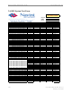
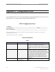
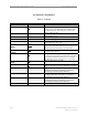
1 RFS Antenna Height and Orientation Per Plan
2 RFS Antenna Mount Plumb Per Axis
3 GPS Antenna Mounted Per Plan
4 Zinc Cold Galvanizing compound used everywhere
5 Coaxial Cables Run Straight (Not Exceeding Bend Radius)
6 Coaxial Cables Tagged and Color Coded Per Plan
7 Connectors and Jumpers Installed and Weatherproofed
8 Cable Hangers, Bands or Ties Spaced up every 3 Feet
9 Antenna Power and Data Cable Continuity Tested
10 Antenna System Sweep Test Performed and Passed
11 SW and Hard Copy of Antenna Sweep Test Results Provided
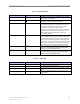
Printed Name
Signature / Date
Company
Phone No.
Printed Name
Signature / Date
Company
Phone No.
Printed Name
Signature / Date
Company
Phone No.
NOTES
Antenna and Feeder System
N/AYES NO
N/AYES NO
N/AYES NO
N/AYES NO
N/AYES NO
N/AYES NO
N/AYES NO
N/AYES NO
N/AYES NO
N/AYES NO
N/AYES NO