
User's Manual

Navini Networks, Inc. Ripwave Base Station I&C Guide
Part #40-00047-00 Rev D v1.0 159
February 28, 2003
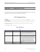
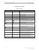
Layer 1 - Antenna Table
Field Name Values Description
Antenna Index
1-8 The number of the antenna (1-8) that maps to a specific
antenna element in the RFS.
Admin Status
Up
or Down Determines if the antenna is transmitting RF. Up means
transmitting; Down means not transmitting.
Power Splitter_I
The real element of the calibrator board characteristics
that is found in the RFS. This information captures the
loss and phase information of the board. The Power
Splitter data is unique to each RFS. An RFS
Configuration CD ships with the equipment. It provides
an RFS script and instructions for selecting the correct
value to match the specific RFS that is physically
installed with the BTS.
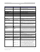
Power Splitter_Q
The imaginary element of the calibrator board that is
found in the RFS. This information captures the loss &
amplitude information of the board. The Power Splitter
data is unique to each RFS. An RFS Configuration CD
ships with the equipment. It provides an RFS script and
instructions for selecting the correct value to match the
specific RFS that is physically installed with the BTS.
RF Tx Gain
0-255 The Transmit gains for each antenna element, ranging
from 0-255, with 0 being the lowest gain. This data is
returned as a result of full calibration.
RF Rx Gain
0-255 The Receive gains for each antenna element, ranging
from 0-255, with 0 being the lowest gain. This data is
returned as a result of full calibration.
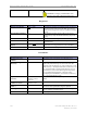
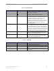
Layer 1 - w0 Table
Field Name Values Description
Sub Carrier Id
1-5 The subcarrier number. Subcarriers are assigned in pairs.
Antenna Index
1-8 The number of the antenna element.
W0 Weight_I
Real elements of the vector used to control ACC spatial
pattern.
W0 Weight_Q
Imaginary elements of the vector used to control ACC
spatial pattern.