
User's Manual

Navini Networks, Inc. Ripwave Base Station I&C Guide
Part #40-00047-00 Rev D v1.0 61
February 28, 2003
Install Surge Protectors
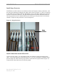
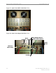
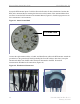
The RFS has ten cable connectors on the bottom of the unit. Eight are antenna connections, with
the connectors alternately numbered from right to left as shown in Figure 31. The two connectors
in the middle are for antenna calibration and data/DC power connections. Install surge protectors
on nine (9) of the RFS connectors – the eight antenna connectors and the calibration connector.
The surge protectors must be installed directly to the RFS to provide protection for the antenna
elements.
Torque the surge protectors to 20-24 inch-pounds.
Figure 31: Surge Protectors
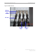
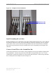
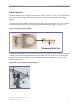
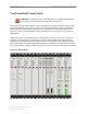
Install Cables Between the RFS & BTS
Connect all of the cables – the eight antenna cables, the calibration cable and the data/power
cable – to the surge protectors on the RFS (Figure 32). For ease of installation, install the cables
from the inside out. Ensure that the proper cable is connected to the proper antenna (Figure 33).
Torque the RF cable connectors to 20-24 inch-pounds.
Surge
Protectors
Surge
Protectors