
User's Manual


Navini Networks, Inc. Ripwave Base Station I&C Guide
Part #40-00047-00 Rev D v1.0 175
February 28, 2003
Appendix F: Base Station Calibration Verification*
Instructions
This procedure and form are created to explain how and what to enter into the Base Station
Calibration Verification spreadsheet, as well as define each cell’s function. The cells that need an
entry are shown in green. This procedure and form are to be used in conjunction with the
Installation & Commissioning manual.
General Information
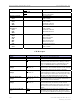
A. Site Name (D4) - Enter the site name or customer designation.
B. BTS ID (D5) - Enter the BTS identification number or customer description.
C. Date (D6) - Excel will enter the current date.
D. Software Release (D7) - Enter the release number of the software load being used.
E. Personnel (D8) - Enter your name.
F. 2.4 GHz (B12) - Enter an X or some other mark in the appropriate box for
the frequency slot that the system will be operating at.**
G. 2.6 GHz (B17-F17) - Enter an X or some other mark in the appropriate box for
the frequency slot that the system will be operating at.**
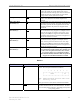
H. Cal Path Loss (average) (H21) - This is a calculated value determined from the
data entered in Section II.
I. Receiver Sensitivity (set in the EMS) (H23) - Enter the same number entered in
the EMS under Air Interface > Layer 1 > General tab > Receiver sensitivity.
J. Test Cable Loss (H24) - Enter the loss of the test cable that will be used to
connect the signal generator to the calibration cable. Do not try to approximate
this value. Measure all test cables before starting any testing. If no additional
cable is necessary, enter zero (0). Include the minus sign, as it is a loss.
K. RF Power Injected at Cal Cable to Get Sensitivity at Antenna (H25) - This is a
calculated value determined from the values in H21-H24.
L. Antenna Power (in the EMS) (H30) - Enter the same number entered in the EMS
under Air Interface > Layer 1 > General tab > Antenna power.
M. Coupler/Test Cable Loss (H31) - Enter the loss of the coupler’s coupled port plus
the test cable that will be used to connect the spectrum analyzer to the BTS’s
output ports. Do not try to approximate this value
. Measure all test items and
cables before starting any testing.
_______________
*Sometimes called the RF Sanity Test.