
User's Manual

Ripwave Base Station I&C Guide Navini Networks, Inc.
178 Part #40-00047-00 Rev D v1.0
February 28, 2003
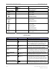
B. Test CHP Card (D76-D83) - These are the jack identifiers for the CHP test card,
which is modified to provide baseband signals to the front panel. Be aware that
the order on the card is not sequential from top to bottom. The first (top) jack is
channel #4, the second jack is channel #2, the third jack is channel #3, and the last
(bottom) jack is channel #1.
C. Noise Level (mVrms) (F76-F83) - Measured baseband noise level of each
channel. This measurement includes noise generated by the BTS (Noise figure)
plus ambient noise of the surrounding environment.
D. Noise + Signal (mVrms) (G76-G83) - The signal level measured when a
Continuous Wave tone is injected at the calibration cable. Tone amplitude is
calculated in cell H25. This is a composite signal including noise.
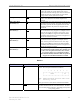
E. Signal (H76-H83) - The calculated signal level. Noise is subtracted from signal +
noise using the following formula: square root of the signal plus noise level,
squared, minus the square of the noise level:
Signal = SQRT ((signal+noise)
2
- (noise)
2
).
F. Signal-to-Noise Ratio (SNR) (I76-I83) - Calculated value of the signal-to-noise
ratio. Determined by the following formula: Log10 of the signal + noise level,
divided by the noise level, multiplied by 20. Dividing gives you the ratio. Taking
the Log10 of the ratio converts to power. Multiple by 20 to convert to dB:
SNR = Log10 (signal+noise/noise)*20
G. Noise Power (J76-J83) - Calculated value of the noise power at the baseband
input to the Channel Processor. Calculated by adding the signal level injected at
the antenna (RX sensitivity) plus the SNR value. Unit of measure is dBm.
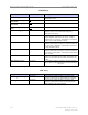
H. Relative Noise Figure (K76-K83) - Calculated noise figure of the system. Since
the noise level includes thermal and ambient noise in addition to the BTS noise
figure, and we have no control over the signal source noise, it is labeled as
“relative” and is then referenced to the thermal noise floor. It is calculated by
subtracting the theoretical thermal noise floor (Ktb) (-106 dBm, in a 6 MHz
bandwidth) from the noise power calculation. This establishes a noise figure that
includes any noise from the signal source as well as the BTS noise figure.
I. RX Gain (DAC Word) (L76-L83) - The hex data generated during calibration for
the receiver gain DAC that controls the IF attenuator. It is found in the EMS
under Air Interface > Layer 1 > Show Configuration > Antenna tab.
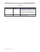
Transmitter Performance
A. Analyzer Readings (A90-B97)
1. Peak - The peak amplitude of the sync signal measured on the spectrum
analyzer. The measurement is taken with the spectrum analyzer in time
domain (0 Hz span) and RBW set for 5 MHz. Sweep time is typically
between 10 and 20 ms. When taking the measurement, the sync signal will
have peaks and valleys associated with it. Make sure to measure the
absolute peak.