
User's Manual

Navini Networks, Inc. Ripwave Base Station I&C Guide
Part #40-00047-00 Rev D v1.0 179
February 28, 2003
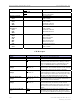
2. RMS - This is a calculated value based on measurements taken on several
occasions, comparing peak power to RMS power on a Rhode & Schwartz
spectrum analyzer. It has been determined that the correction factor for
peak to average on a standard spectrum analyzer is 9.5dB. This correction
factor is the default entry in this section. If it is possible to make the RMS
measurement with the proper equipment, then that is the preferred method.
The calculation is very straight-forward:
Peak Power minus 9.5dB = Power RMS.
B. P out Transceiver (D90-E97) - Power peak and Power RMS are calculated values
using the value from the spectrum analyzer readings and the value entered for
coupler/test cable loss. (Cell H31)
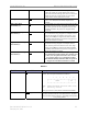
C. Power at Antenna (RMS) (G90-G97) - Calculated value using the P out of the
transceivers and the Cable Loss plus the inherent loss of the RFS.
D. Radiated Power (RMS) (I90 - I97) - Calculated value using Power at the antenna
and the value entered for antenna gain. (Cell H32)
E. TX Gain (DAC Word) - The hex data generated during calibration for the
transmit gain DAC that controls the IF attenuator. It is found in the EMS under
Air Interface > Layer 1 > Show Configuration > Antenna tab.
F. Max Power Deviation Across All Antennae (E99, G99, I99) - Calculated value
showing the deviation between the lowest power antenna and highest power
antenna for each column.