
User's Manual

Navini Networks, Inc. Ripwave Base Station I&C Guide
Part #40-00047-00 Rev D v1.0 185
February 28, 2003
Step 1. Ensure that the Base Station has successfully completed calibration and RF sanity
measurements at the frequency and TX/RX signal levels that were determined during
the site survey. Ensure that the Base Station is powered on and able to TX/RX data.
Step 2. Create a CPE Descriptor, and assign it to the CPE’s to be used for the Drive Study:
CPE Descriptor Parameters
Name: Drive Study
Index: Next available number
Priority: 1
UpLink Max Bandwidth: 64
UpLink Min Bandwidth: 32
DownLink Max Bandwidth: 96
DownLink Min Bandwidth: 64
Other parameters: Use defaults.
Step 3. Mount an omni-directional antenna on the roof of the vehicle. This will serve as the
antenna for the CPE.
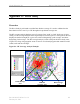
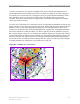
Step 4. Bring the RF cable from the omni-directional antenna into the vehicle through the
window. Attach the antenna to the antenna input of the CPE. The rotating upright
antenna on the CPE needs to be removed to perform this step. You will also need to
disconnect the patch antennas inside (Figure G3).
Figure G3: Patch Antennas