
User's Manual


Navini Networks, Inc. Ripwave Base Station I&C Guide
Part #40-00047-00 Rev D v1.0 213
February 28, 2003
Appendix K: Install Connectors on Cables
The following procedures are for installing Times connectors on LMR cable. The procedure may
vary for different types of connectors and cables.
You will need to install connectors on both ends of each cable. Install EZ-600 N-type male
connectors on all LMR 600 cables. Install EZ-400 N-type male connectors on all LMR 400
cables. The steps below can be used for both connectors.
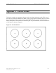
Step 1. Ensure that the cable is cut straight.
Step 2. Slide the heat shrink boot and crimp ring onto the cable. Strip the cable end using the
ST-600-EZ prep/strip tool by inserting the cable into End 1 and rotating the tool.
Remove any residual plastic from the center conductor.
Step 3. Insert the cable into End 2 of the ST-600-EZ prep/strip tool and rotate the tool to
remove the plastic jacket.
Step 4. Debur the center conductor using the DBT-01 deburring tool.
Step 5. Flare the braid slightly and push the connector body onto the cable until the connector
meets resistance and then snaps into place. Then slide the crimp ring forward, creasing
the braid.
Step 6. Slide the crimp ring back, and trim the excess braid at the crease line. Slide the crimp
ring forward until it butts up against the connector body.
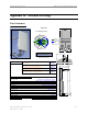
Step 7. Position the heavy duty HX-4 crimp tool with the appropriate dies (.510”hex) directly
behind and adjacent to the connector body, and crimp the connector. The crimp tool
automatically releases when the crimp is complete.
Step 8. Position the heat shrink boot as far forward on the connector body as possible without
interfering with the coupling nut. Use a heat gun to shrink the heat shrink and form a
weather tight seal.
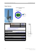
Step 9. Label all cables on both ends. Label the nine LMR-600 cables RFS 1 through RFS 8
and CAL. Label the two LMR-400 cables GPS 1 and GPS 2. Label the data/power
cable (from the supplier) as POWER.