
User's Manual


Navini Networks, Inc. Ripwave Base Station I&C Guide
Part #40-00047-00 Rev D v1.0 219
February 28, 2003
Appendix N: Rectifier/BBU Specifications
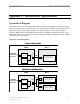
System Block Diagram
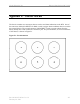
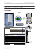
Navini Networks uses a 1000 Watt Rectifier/Battery Backup Unit (BBU) for the Ripwave Base
Transceiver Station (BTS) combo chassis, and a 1500 watt Rectifier/BBU for the Ripwave BTS
split chassis. The system diagrams in Figure N1 depict the current flow from incoming AC
voltage to BBU and the converted power into the BTS. The BBU is designed to provide a four-
hour battery backup for the BTS. The rectifier is designed with hot-swappable modules. Module
redundancy of N+1 is required.
Figure N1: System Diagrams
Combo Chassis (ISM)
AC INPUT:
180-265 VAC
OR 115VAC
27V
AC/DC
Converter
Battery
200 AH
B B U B T S
Circuit
Breaker
Inner Loop Fans
Power @ 1000 Watts
50 Amp
AC INPUT:
180-265 VAC
OR 115VAC
27V
AC/DC
Converter
Battery
200 AH
B B U B T S
Circuit
Breaker
Inner Loop Fans
Power @ 400 Watts
Inner Loop Fans
Power @ 1100 Watts
Digital Shelf
RF Shelf
50 Amp
20 Amp
Split Chassis (MMDS/WCS)