
User's Manual

Ripwave Base Station I&C Guide Navini Networks, Inc.
224 Part #40-00047-00 Rev D v1.0
February 28, 2003
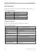
Alarm & Control
The Alarm and Control Relay has dry contact: open for alarm, normally grounded (safe), for the
following:
• AC line failure
• Low battery voltage
• Rectifier failure
• (Optional) - self test go/no-go, if applicable
• (Optional) - charger failure, if provided
• (Optional) - output voltage sense line
• Common chassis ground
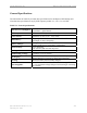
Mechanical Configuration
The following list covers the mechanical configuration requirements for the Ripwave BTS
backup unit. The internal rectifier should be 19 inch rack-mountable. The rectifier shall consist
of N+1 hot swappable modules. If one module fails, there must be enough power handling
capability to provide full output power for a load of 1KW.
• Rectifiers to provide internal cooling. No external forced air provided.
• Acoustic Noise less than 60dBA, 1 meter from front.
• Rectifier to provide front panel indicators: AC ON, Module Failure.
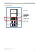
• The maximum dimensions of the rack are: 84” (H) x 19” (W).
• The BBU shall be placed in a single 19-inch rack. See diagram in Figure N2.
• Power exits: rear preferred; front is not acceptable.