
User's Manual

Ripwave Base Station I&C Guide Navini Networks, Inc.
102 Part #40-00047-00 Rev D v1.0
February 28, 2003
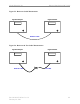
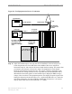
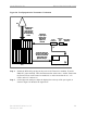
Figure 55: Coupler Measurement
Test Procedure
Step 1. Connect a test cable to the Signal Generator and to the Spectrum Analyzer. This will be
the reference cable (Figure 53).
Step 2. Turn on RF Power on the Signal Generator.
Step 3. On the Spectrum Analyzer, set the reference level so that the signal peak is no more
than 1 division down from the top of the screen, but does not go past the top of the
screen.
Step 4. Press the Peak Search button on the Analyzer. If the marker is bouncing excessively,
turn on the averaging function. Adjust averaging to stabilize the marker but not slow
down the sweep too much. Once the marker is stabilized, press Peak Search again to
make sure you are on the peak, then press marker delta. This establishes the reference
point for measurements.
Step 5. Turn off RF Power on the Signal Generator. Disconnect the reference cable from the
Spectrum Analyzer.
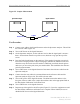
Step 6. Connect the other test cable to be measured between the reference cable and the
Spectrum Analyzer (Figure 54). This will be the test cable.
Step 7. Turn on RF power on the Signal Generator. The delta between the markers is the
loss/gain of the test cable or the coupler. Record that value in the appropriate field on
the Base Station Calibration Verification Form.
Step 8. Turn off RF Power on the Signal Generator.
Step 9. Repeat steps 6 through 8 for the RF coupler (Figure 55). Leave the equipment on until
the Base Station calibration verification test is complete. When finished, be sure to
disable the RF Power on the Signal Generator.
Spectrum Analyzer Signal Generator
Reference Cable
Coupler
Test Cable
Spectrum Analyzer Signal Generator
Reference Cable
Coupler
Test Cable